
Design
10 questions: O-ring data sheets
In this short article, we answer the 10 most important questions about the correct design of O-ring data sheets in a simple and understandable way.
A minimum degree of compression between the component surfaces is necessary for O-rings to develop their sealing effect. The necessary pressure comes from the machine elements to be sealed on the one hand and from pressurized media on the other.
However, O-rings are subject to particularly high operating pressures. This can lead to mechanical damage and permanent deformation. Here you can read how the most important factors interact under pressure with O-ring hardness and sealing gap.
The sealing effect of an O-ring only comes about through the elastic deformation of its cross-section in the installation space. Let’s think of a flange gasket: The fitter inserts the sealing element with a circular cross-section into the groove of the housing.
When the cover plate is screwed on, pressure is created which deforms the cross-section of the O-ring. In this case, the deformation occurs in the axial direction between the groove base and the sealing surface. The cross-section of the elastomer seal is no longer round, but oval. In this way, the sealing element seals any unevenness in the sealing surfaces.
With a radial seal, i.e. a classic piston or rod seal, there is a radial gap between the inner and outer machine part.
In sealing technology, this dimension is referred to as the sealing gap. This gap is particularly crucial when it comes to sealing between two rooms with different pressure levels. This is because the higher pressure moves the O-ring towards the side of the groove facing away from the pressure.
This does not necessarily have a negative effect on the function of the seal. Within certain limits, the additional surface pressure can support the sealing performance.
However, particularly high pressures can put a great deal of strain on the sealing system. They press the O-ring into the sealing gap, causing mechanical damage. High temperatures and abrupt pressure surges contribute to this.
The hardness of the O-ring indicates how easily it can be deformed under the effect of pressure. When it is pressed between the sealing surface and the installation groove, it adapts to the component contours and also seals fine scratches or other defects in the surfaces.
The lower the hardness of the O-ring, the less pressure is required for the necessary compression.
Two methods are used to measure the hardness of O-rings: Shore hardness and IRHD. Both measuring methods are based on the fact that a defined test specimen with a certain weight acts on the material sample. The hardness according to Shore or IRHD is determined by the penetration depth. Both methods use scales from 0 to 100.
A hardness of 100 indicates that the test specimen has not penetrated the sample at all. The Shore hardness of the O-ring material is a key specification in the technical data sheet. The characteristic value is often a decisive criterion when selecting materials.
Crucial for practitioners: The data sheets for O-ring materials usually contain the Shore hardness determined on material samples. Deviations between the Shore hardness of a standard sample and the hardness of the end product O-ring cannot be avoided.
The geometric differences between the sample and the finished part are too great. The methods are also susceptible to measurement errors.
Contrary to popular belief, a harder O-ring is not automatically better than a less hard one. It is true that harder O-rings deform less easily when subjected to pressure. This has advantages in terms of the durability of the seal.
Harder O-rings also adapt less well to the finest unevenness in the sealing surfaces. The correct dimension for the hardness of an O-ring therefore always results from the overall operating conditions and the design of all components of the sealing system.
However, the Shore hardness is not solely responsible for the deformation resistance of an O-ring. The compression set also plays an important role. O-rings not only undergo elastic but also plastic deformation under pressure.
This should be as low as possible so that the O-ring can adapt to changing operating conditions over a long period of time. The lower the compression set, the less permanent deformation an O-ring retains after it has been relieved.
First of all, the standard guide values for the design of the groove depth and cord diameter: The degree of pressure-induced deformation of the O-ring in the installation position is determined by the compression. This is the percentage of the cord diameter by which the cross-section is compressed.
Typical compression for the static use of O-rings is between 15 and 30 percent. The width of the groove should be designed so that the medium can penetrate evenly from the side under pressure.
A frequently used guideline: The rectangular cross-sectional area of the groove should be approximately 1.25 times the round cross-sectional area of the O-ring. The media pressure presses the O-ring not only against the flank of the groove, but also against the sealing gap between the components.
The sealing gap results from the diameter clearance between the two components to be sealed. If the pressure exerts a sufficiently high force on the seal, the O-ring can be pressed into this gap. A larger sealing gap favors this process. This applies in particular to radial seals.
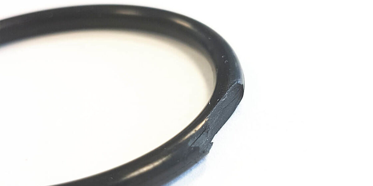
O-rings with a lower Shore hardness can be pressed into the sealing gap at a lower pressure. This can lead to permanent deformation of the elastomer seal and thus to its failure. This also results in the damage pattern of gap extrusion: Here, the groove edge shears the material off the O-ring in thin layers.
Such mechanical damage to the O-ring is the most common category of cause for the failure of an O-ring seal, even before ageing and media attack.
In pressurized applications, the most direct solution is usually not an option: the system pressure cannot usually be reduced to meet the sealing requirements. Instead, the sealing system needs to be optimized.
For applications with high pressure loads, the designer should provide O-rings with a higher Shore hardness. With common base elastomers such as FKM or NBR, Shore hardnesses in the usual range of 70 to 90 Shore A can be achieved by selecting different compounds.
Silicones such as VMQ or FVMQ are less suitable for printing applications. The sealing gap should be particularly small here. Polyurethane materials withstand high system pressure much better. They have a very low compression set.
This means that they return to their original shape to a large extent after being relieved. O-rings with a higher cord thickness have more reserves and therefore retain their sealing effect for longer, even with gap extrusion. In addition, fabric reinforcements or extrusion-resistant support rings can increase the durability of the seal.
Only after the choice of materials has been exhausted should constructive measures follow. General tables provide information on the design of the sealing gap depending on the O-ring. They stipulate the following for an O-ring with a hardness of 70 Shore A and a cord thickness of between 2 and 3 millimeters: At a pressure load of up to 70 bar, the sealing gap must not exceed 0.08 millimeters.
An O-ring of the same cord thickness with 90 Shore A, on the other hand, can be used in an installation space with a gap of up to 0.15 millimeters under the same pressure load.
The sealing gap can be reduced by manufacturing the components with the smallest possible tolerances. However, the economic efficiency requirements limit this approach. Installation grooves for O-rings are cut into rotationally symmetrical components using a turning tool.
A corresponding groove cutter is used for flange covers. Improving the precision of these processes or enhancing the end result through downstream processes such as grinding drives up production costs. Just as important, however, is how exactly the two components are positioned in relation to each other when installed. For example, guides can effectively limit the eccentricity of the workpieces.
The design and production optimization of the groove design has its limits: Tight tolerances and high surface qualities represent a considerable cost factor. In order to keep the cost of a high-performance seal within economic limits, the other components of the sealing system must also be optimized for the pressure application.
Our application experts will be happy to support you in your search for holistic solutions.
“I am convinced that we should share our knowledge with the world. I hope I have been able to answer all your questions. If you have any further questions, please feel free to contact us at any time. We will be happy to help you.”

Lord of the O-rings
Author of the sealing academy
In this short article, we answer the 10 most important questions about the correct design of O-ring data sheets in a simple and understandable way.
In this short article, we answer the 10 most important questions about the correct design of O-ring grooves in a simple and understandable way.
In this short article, we answer the 10 most important questions about the correct storage of O-rings in a simple and understandable way.