
O-Ring Groove Calculation
Almost all O-ring failures come down to poorly designed grooves. Choose the seal type and cord thickness and the tool returns the matching groove dimensions as reference values based on ISO 3601.
← All O-Ring Tools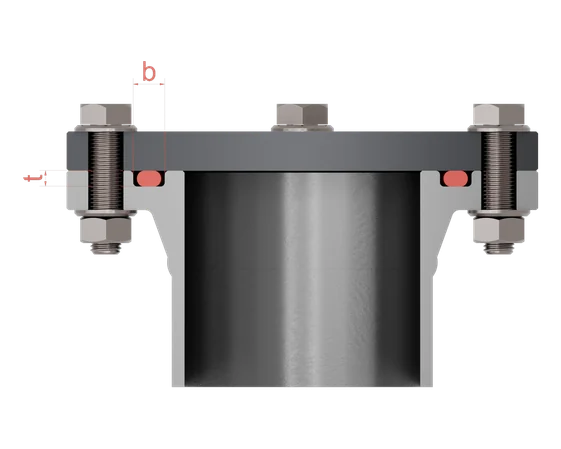
All values in millimetres. Tolerances per ISO 3601-1, class B (cord thicknesses above 8.4 mm are not standardised there), groove dimensions as reference values based on ISO 3601-2. Intermediate sizes are interpolated between the table values. For the flange seal the groove inner diameter follows the selected pressure direction. For the piston seal the O-ring sits on the groove bottom with 2% stretch (dynamic 3% at most, static 5% at most). For the rod seal it rests against the groove bottom on the outside and is compressed there by 3% at most. All values are application-dependent reference values.
Disclaimer
This tool provides non-binding reference values as a design aid based on ISO 3601. We accept no liability for the accuracy, completeness or suitability of the values in a specific application. The respective data sheet always prevails. Please verify the design on your own responsibility and consult us in case of doubt. Liability for damages arising from the use of this tool is excluded to the extent permitted by law.
How do I use the groove calculation?
Which materials does the groove calculation apply to?
What is a flange seal?
What is a piston seal?
What is a rod seal?
Difference between static and dynamic?
Disclaimer, errors and changes
Recommended groove width (GW) and groove depth (GD) per cord thickness, separated by seal type and static or dynamic use. All dimensions in millimetres, reference values for the design.
| Cord thickness mm | Flange seal | Piston seal | Rod seal | |||||||
|---|---|---|---|---|---|---|---|---|---|---|
| static | static | dynamic | static | dynamic | ||||||
| GW | GD | GW | GD | GW | GD | GW | GD | GW | GD | |
| 1.00 | 1.90 | 0.70 | 1.58 | 0.70 | 1.58 | 0.85 | 1.58 | 0.70 | 1.58 | 0.85 |
| 1.50 | 2.80 | 1.10 | 2.19 | 1.05 | 2.19 | 1.27 | 2.19 | 1.05 | 2.19 | 1.27 |
| 1.78 | 3.20 | 1.30 | 2.53 | 1.30 | 2.53 | 1.50 | 2.53 | 1.30 | 2.53 | 1.50 |
| 2.00 | 3.40 | 1.50 | 2.78 | 1.50 | 2.78 | 1.65 | 2.78 | 1.50 | 2.78 | 1.65 |
| 2.50 | 3.90 | 1.90 | 3.37 | 1.90 | 3.37 | 2.12 | 3.37 | 1.90 | 3.37 | 2.12 |
| 2.62 | 4.00 | 2.00 | 3.51 | 2.00 | 3.51 | 2.22 | 3.51 | 2.00 | 3.51 | 2.22 |
| 3.00 | 4.60 | 2.30 | 3.98 | 2.30 | 3.98 | 2.55 | 3.98 | 2.30 | 3.98 | 2.55 |
| 3.53 | 5.30 | 2.70 | 4.67 | 2.70 | 4.67 | 2.95 | 4.67 | 2.70 | 4.67 | 2.95 |
| 4.00 | 6.00 | 3.10 | 5.23 | 3.10 | 5.23 | 3.30 | 5.23 | 3.10 | 5.23 | 3.30 |
| 4.50 | 6.50 | 3.50 | 5.90 | 3.50 | 5.90 | 3.80 | 5.90 | 3.50 | 5.90 | 3.80 |
| 5.00 | 7.40 | 3.90 | 6.48 | 3.90 | 6.48 | 4.30 | 6.48 | 3.90 | 6.48 | 4.30 |
| 5.33 | 7.60 | 4.20 | 6.86 | 4.20 | 6.86 | 4.60 | 6.86 | 4.20 | 6.86 | 4.60 |
| 5.50 | 7.60 | 4.40 | 7.05 | 4.40 | 7.05 | 4.80 | 7.05 | 4.40 | 7.05 | 4.80 |
| 6.00 | 8.00 | 4.80 | 7.59 | 4.80 | 7.59 | 5.20 | 7.59 | 4.80 | 7.59 | 5.20 |
| 6.50 | 8.40 | 5.30 | 8.17 | 5.30 | 8.17 | 5.60 | 8.17 | 5.30 | 8.17 | 5.60 |
| 7.00 | 8.70 | 5.70 | 8.68 | 5.80 | 8.68 | 6.00 | 8.68 | 5.80 | 8.68 | 6.00 |
| 7.50 | 9.50 | 6.20 | 9.29 | 6.30 | 9.29 | 6.50 | 9.29 | 6.30 | 9.29 | 6.50 |
| 8.00 | 9.80 | 6.70 | 9.88 | 6.80 | 9.88 | 7.00 | 9.88 | 6.80 | 9.88 | 7.00 |
| 9.00 | 11.20 | 7.60 | 11.14 | 7.70 | 11.14 | 7.90 | 11.14 | 7.70 | 11.14 | 7.90 |
| 10.00 | 12.20 | 8.60 | 12.38 | 8.60 | 12.38 | 8.80 | 12.38 | 8.60 | 12.38 | 8.80 |
GW groove width · GD groove depth · all values in mm. Reference values for groove design; material, tolerances and operating conditions prevail. Check dimensions with our O-Ring Groove Calculation.