
ISO 3601: O-Ring Standard, Dimensions, and Tolerances
ISO 3601 is the most important O-ring standard worldwide. It is divided into five parts and forms the basis for the design, dimensioning, and evaluation of O-rings. Here you can learn what each part covers and what is important when it comes to tolerance classes, material properties, and support rings.

- ISO 3601 is the most important international standard for O-rings and is divided into five parts. In Germany, it is known as DIN ISO 3601 and replaced DIN 3771 in 2010.
- Part 1 covers dimensions and tolerances, Part 2 covers mounting spaces, Part 3 covers quality, Part 4 covers support rings, and Part 5 covers materials.
- There are two tolerance classes for the inner diameter: Class A, with tighter tolerances as specified in AS568, and Class B for general applications. According to Class B, an inner diameter of 100 mm may vary by ±0.82 mm.
- The grade characteristics N, S, and CS specify which deviations in shape and surface finish are permissible.
- Support rings in accordance with Section 4 protect O-rings from gap extrusion under high pressure.
What is ISO 3601?
ISO 3601 is by far the most important O-ring standard at the international level. It is divided into five parts and forms the basis for the design and evaluation of an O-ring. In Germany, it has been adopted as DIN ISO 3601 and replaced the former DIN 3771 in 2010.
| Section | Contents |
|---|---|
| ISO 3601-1 | Inner Diameter, Cord Thicknesses, Tolerances, and Designation |
| ISO 3601-2 | Enclosures for General Applications |
| ISO 3601-3 | Shape and Surface Deviations (Quality) |
| ISO 3601-4 | Support rings to prevent gap extrusion |
| ISO 3601-5 | Requirements for Elastomer Materials |
The Standard in Phases
The first edition was published in 1978 and essentially adopted the metric dimensions specified in DIN 3771. However, even back then, the inch-based sizes specified in the American AS568 standard were the most widely used worldwide. It wasn’t until the 2008 edition that these sizes were included, converted to millimeters. Since then, a single standard has covered the vast majority of O-ring sizes used worldwide.
Thus, Parts 1 and 2 provide significant added value for designers around the world: For a wide range of standard applications, the tables provide all the key guidelines for an effective sealing system. Parts 3 and 5 supplement this with mandatory quality criteria for manufacturing and formulation.
Part 1: How is an O-ring correctly defined?
In general, an O-ring is fully described by two dimensions: the inner diameter d1 and the wall thickness d2, for example, 12.42 × 1.78 mm. Part 1 specifies which combinations are considered standard sizes, what the permissible tolerances are, and how a size is designated.
If the combination of inner diameter and cord thickness corresponds to a standard size, there are two advantages:
- The item probably has a shorter delivery time or may even be in stock.
- Compared to custom sizes, the price is often much better.
Tolerance Classes A and B
ISO 3601-1 specifies two tolerance classes for the inside diameter:
- Class A: tighter tolerances, equivalent to those of AS568. For industrial and aerospace applications where the application or installation space requires tight tolerances.
- Class B: slightly wider tolerances for general applications—that is, standard O-rings available on the market.
If no grade is specified, Class B is generally assumed in practice. If you require tighter tolerances, be sure to explicitly specify Class A.
Class B by the Numbers
The permissible deviation increases with the inner diameter. Fixed increments apply to the wire size; here are the five standard wire sizes specified in the standard, in both inch and metric units:
| Inner Diameter | Tolerance Class B |
|---|---|
| 5 mm | ±0.15 mm |
| 10 mm | ±0.19 mm |
| 25 mm | ±0.30 mm |
| 50 mm | ±0.48 mm |
| 100 mm | ±0.82 mm |
| 200 mm | ±1.51 mm |
| 300 mm | ±2.14 mm |
| 500 mm | ±3.51 mm |
| 1,000 mm | ±6.48 mm |
| Line thickness | Tolerance |
|---|---|
| 1.78 and 1.80 mm | ±0.08 mm |
| 2.62 and 2.65 mm | ±0.09 mm |
| 3.53 and 3.55 mm | ±0.10 mm |
| 5.30 and 5.33 mm | ±0.13 mm |
| 6.99 and 7.00 mm | ±0.15 mm |
Inner diameter 100 ±0.82 mm, i.e., 99.18 to 100.82 mm. Cord thickness 3.53 ±0.10 mm, i.e., 3.43 to 3.63 mm. Calculate the compression and fill ratio of your groove using these limits, not just the nominal dimension.
Values according to ISO 3601-1 Class B. Our O-ring Tolerance Calculator shows the tolerance for each inner diameter up to 2,000 mm.
You can find all standard sizes in our ISO 3601 table and in the O-ring tables; the article on O-ring designations explains how each size is labeled.
Part 2: How Do I Optimize the Design of an O-Ring?
The correct sizing of an O-ring is crucial for long-term sealing performance. Since 2008, Part 2 has specified the installation clearances for general fluid power applications, including coordinated guidelines for compression and elongation. You should always refer to this information when designing O-rings and installation clearances.
In practice, two cases are important here:
- The installation space is available, and we are looking for the right O-ring.
- The O-ring is provided, and the appropriate installation space is being sought.
For both cases, the standard provides tables, broken down by the three installation types:
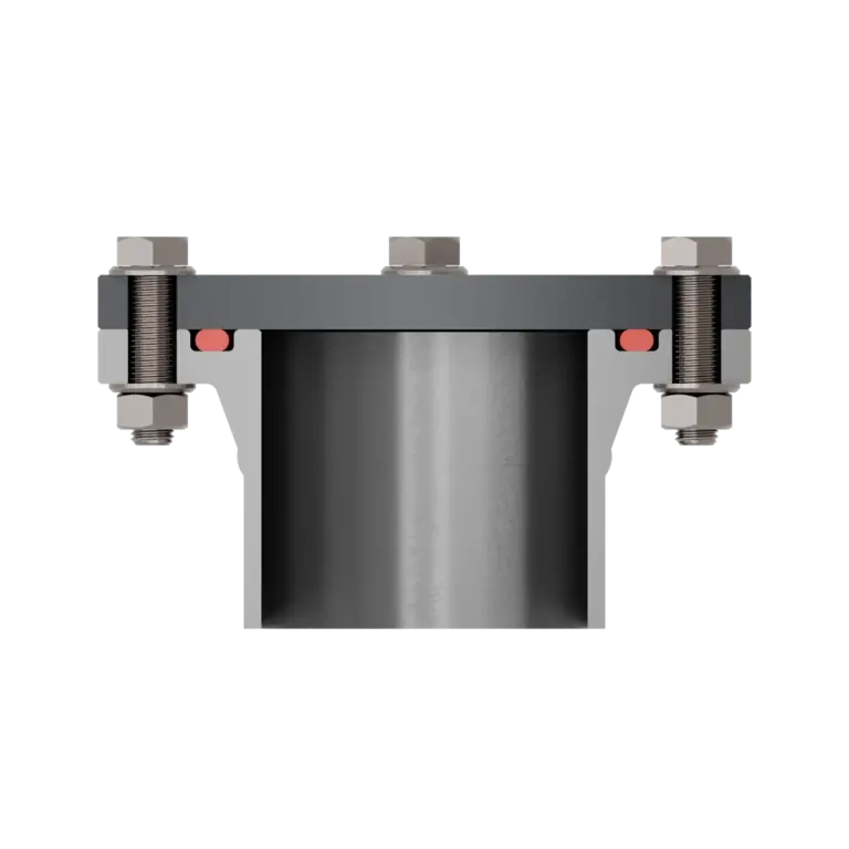
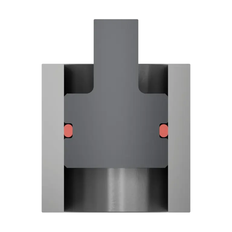
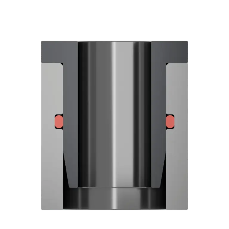
Radially pressed, groove in the housing. Whether static or dynamic, the ring is compressed.
For each installation type, the standard specifies the dimensions of the groove. These dimensions describe a groove:
- b
- Groove width
- t
- Groove depth
- d2
- Cord thickness before installation
- r1
- Radius at the bottom of the groove
- r2
- Radius at the edge of the groove
The groove dimensions depend on the cord thickness, the installation method, and whether the seal is stationary (static) or moving (dynamic). You can calculate the groove width and depth for your size using our groove calculator. Our article on O-ring design explains how installation space, compression, and expansion interact.
Part 3: What Are the Key Factors in O-Ring Quality?
The manufacturing quality of an O-ring is evaluated based on six characteristics:
ISO 3601-3 specifies the permissible deviations for each of these characteristics. This establishes a standard that serves as the basis for evaluating an O-ring. The maximum permissible deviation depends on the specific characteristic:
For general applications. Nearly all O-rings are manufactured this way.
For high-performance industrial applications and the aviation industry.
For specialized aviation applications and oxygen systems.
Virtually all O-rings are manufactured to standard quality grade N. If an O-ring is to be manufactured to grade S or CS, this must always be specified. The more critical the application, the tighter the tolerances for dimensional deviations. Meeting these tolerances requires significant effort in both manufacturing and testing; accordingly, the costs are significantly higher than those for standard quality. To learn how we test for quality, read our article on O-ring quality control.
Part 4: What types of support rings are there?
The fourth part of the standard deals with support rings, also known as anti-extrusion rings. Depending on the cord thickness specified in Part 1, it assigns support rings with specific profile dimensions to the O-rings. These rings protect O-rings from excessive pressure.
High pressure—and, above all, rapidly changing pressure conditions—can cause mechanical damage to the O-ring. On the side facing away from the pressure, the O-ring is pressed into the sealing gap, and sharp groove edges shear off parts of the O-ring. This type of damage is called gap extrusion.
A support ring on the non-pressure side serves as a countermeasure. Under load, the hard support ring deforms and closes the sealing gap without sealing it. This prevents the O-ring from flowing into the gap. ISO 3601-4 defines five designs:
Here's How to Position the Support Ring Correctly
- On the side not being printed on, when the printing direction alternates between both sides.
- Concave designs rest against the O-ring with their concave side.
- For each support ring, the groove becomes wider by the width of that ring. The groove dimensions specified in ISO 3601-2 are designed accordingly.
- Support rings are usually made of PTFE, or sometimes of POM or PA.
The appropriate design depends primarily on the accessibility of the groove and the pressure conditions. It also depends on whether the seal is stationary or moving. For more information on behavior under load, see the article “O-Rings Under Pressure.”
Part 5: What Properties Must an Elastomer Material Have?
Exposure to media, temperature, and pressure place highly specific demands on O-ring materials. It is not just a matter of having a high-performance base elastomer. The formulation must also be selected so that the material properties match the operating conditions. Whether they do so is demonstrated by characteristic values for mechanical properties as well as temperature and aging behavior.
Since its first edition in 2002, ISO 3601-5 has specified requirements for O-ring materials. Initially, it served more as a general selection guide based on the contact medium. The 2015 edition marked a significant step forward: It specifies requirements for common materials at specific hardness levels, namely NBR, HNBR, FKM, EPDM, VMQ, and ACM. Part 5 does not cover high-performance materials such as FFKM; for those, the manufacturers’ data sheets apply.
In addition to the formulation, the manufacturing process also influences the properties of the finished part, particularly the critical step of vulcanization. This is why certain requirements apply to the finished O-ring. Tests include hardness, tensile strength, elongation at break, and compression set, as well as aging under heat and storage in reference media. In practice, these parameters indicate whether an O-ring is sufficiently vulcanized.
If an O-ring complies with Part 5, you are equally protected against significant deviations in formulation and vulcanization. Our article “O-Ring Materials” compares the available materials and their suitable applications.
What information must be included on data sheets in accordance with ISO 3601?
The O-ring standard does not prescribe a specific format for data sheets. In practice, however, these five pieces of information have become standard:
Designation according to ISO 1629, for example, FKM or EPDM.
Resistance to the penetration of a test specimen. Learn more about Shore hardness.
Permanent deformation caused by pressure and heat. The smaller the value, the better the springback is maintained.
In addition, the following information is also useful:
We answer the question of what to look for when reading a data sheet in " 10 Questions About O-Ring Data Sheets."
What other dimensional standards are there besides ISO 3601?
In addition to ISO 3601, there are other national and international dimensional standards for O-rings. You can find a detailed comparison in the O-Ring Tables Guide.
| Standard | Origin | Unit |
|---|---|---|
| ISO 3601 | International | metric, plus the inch-based sizes from AS568 |
| DIN 3771 | Germany, until 2010 | metric, superseded by ISO 3601 since 2010 |
| AS568 | SAE, Aviation | Inches (leading) |
| BS 1806 | United Kingdom | Inches |
| BS 4518 | United Kingdom | metric |
| SMS 1586 | Sweden | metric |
| JIS B2401 | Japan | metric and imperial |
| NF T 47-501 | France | metric |
Clicking on the size opens the size chart.
Tables and Tools
Frequently Asked Questions
Which O-rings fall under ISO 3601-1 Class A?
Which O-rings fall under ISO 3601-1 Class B?
How many parts does ISO 3601 consist of?
What do the variety characteristics N, S, and CS stand for?
What does "slot extrusion" mean in the context of O-rings?
Which standard did DIN 3771 replace?
Is there a DIN standard for O-rings?