
O-Ring Design: Groove and Installation Dimensions
An O-ring seals because it is pressed into its groove. It is properly designed when the compression, fill ratio, and elongation are within the target range and the material is suitable for the temperature, medium, and pressure. Here you will find the key specifications, the installation dimensions for the flange, piston, and rod, and the guidelines for the inner diameter.

- Compression: static 15–30% of the cord thickness, 10–20% for FFKM, dynamic 6–20%. The fill ratio remains below 85%.
- Choose standard sizes according to ISO 3601: They are the most readily available, and there are matching installation dimensions for them.
- The inner diameter is determined by the installation type: flange aligned with the direction of pressure, piston stretched by 1–6%, rod with a 1–3% external oversize.
- Always evaluate temperature in relation to the medium: FKM withstands temperatures up to +200 °C in air, but only up to 120 °C in steam.
- Under pressure: harder material, smaller sealing gap, and, at higher pressures, support rings.
How It Works: Compaction
With an O-ring seal, it’s all about the compression between the sealing surfaces. The ring is pressed flat into the groove, filling in the fine irregularities of the surfaces and compensating for minor misalignments. Under pressure, the medium also pushes the ring against the side facing away from the pressure, pressing it more firmly against the sealing surfaces.
The groove is designed so that the press fit is sufficient even if the ring shrinks slightly in the medium or if the tolerances of the components combine in an unfavorable way. However, it must not be pressed in too tightly, otherwise friction and permanent deformation will increase.
Three key figures for each groove
By measuring compression, fill level, and elongation, you can test any installation space—even one that isn't listed in any table:
(d2 − t) / d2 × 100Thicker cords are compressed less tightly; the thickest ones in our table are compressed by 14%, just under 15%. For FFKM, make the groove slightly deeper.
(π × d2² / 4) / (b × t) × 100The ring needs space to accommodate thermal expansion and swelling; at high temperatures, it needs even more clearance.
(Nutgrund-Ø − d1) / d1 × 100Greater stretching makes the cord thinner and reduces the compression. Instead, the ring is slightly compressed against the rod.
Here are the three key figures for the standard line weights, along with the groove dimensions from our table:
O-Ring Tables as a Guide for Sizing
The inner diameter d1 and the cord thickness d2 determine the dimensions of an O-ring. Together with the groove depth, these factors determine the compression when the O-ring is installed. Standard sizes offer three advantages:
- They are readily available, often in stock.
- Standardized tolerances apply to the prefabricated parts.
- There are specific installation dimensions for them.
ISO 3601 is the global standard for O-ring sizes and links the dimensions to corresponding installation spaces. This allows you to find the right size for a given installation space—or, conversely, the installation space for a given O-ring—always with the goal of keeping the compression within the target range. All standard sizes are listed in our O-ring tables; the article on ISO 3601 explains how the standard is structured. You can measure an existing O-ring using our guide on measuring O-rings.
How to Determine the Inner Diameter d1
Select the largest cord size that the installation space allows. The inner diameter is determined by the installation type. With a flange seal, the ring is statically and axially compressed; the direction of pressure determines which side it contacts:
The ring is mounted on the outside. Its outer diameter corresponds to the outer diameter of the groove, with a0–3% reduction.
The ring fits on the inside. d1 corresponds to the inner diameter of the groove, expanded by0–3%.
Internal pressure: The outer diameter of the ring should be between 100 and 103 mm. With d1 = outer diameter − 2 × d2, an inner diameter of 92.9 to 95.9 mm is appropriate. External pressure: With a groove width of 5.30 mm, the inner diameter of the groove is 89.4 mm; with 0–3% elongation, d1 ranges from 86.8 to 89.4 mm. Select a standard size from this range for each direction of pressure.
For pistons and rods, the ring is radially pressed into place. d1 is determined from the groove bottom diameter and the allowable elongation or compression; the examples apply to d2 = 3.53 mm, static:
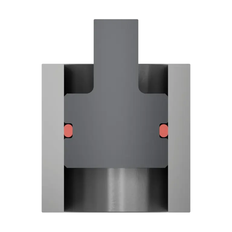
Groove in the piston. Stretch the ring 1–6% onto the bottom of the groove; dynamically, no more than 3%.
d1 = Groove bottom diameter / (1.01 to 1.06)
Bore 50 mm, t 2.70 mm: Groove bottom diameter 44.6 mm, d1 42.1 to 44.2 mm
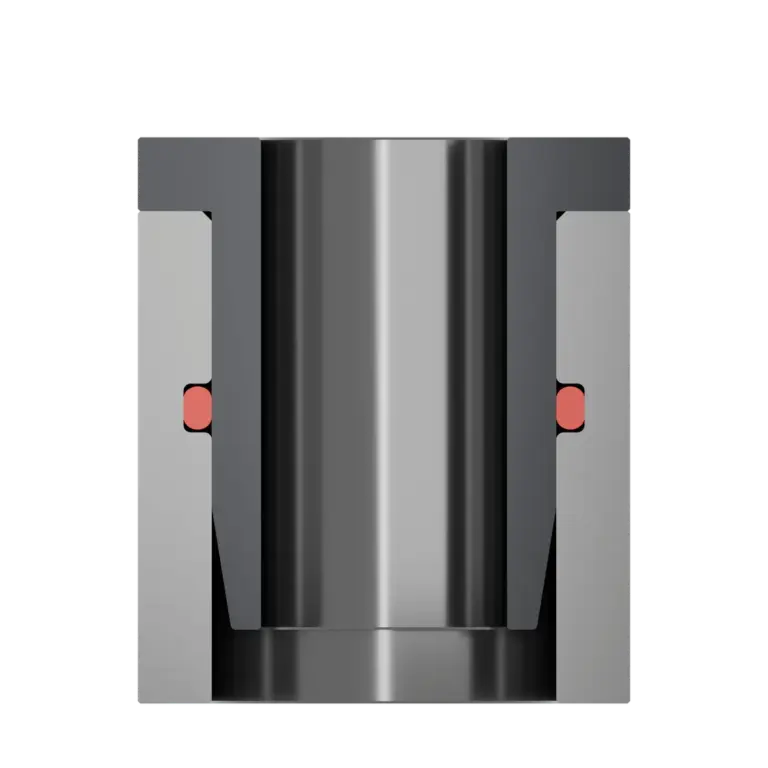
Groove in the housing. Select a ring outer diameter that is 1–3% larger than the groove base diameter; for d1 values of 250 mm or greater, up to 5%.
d1 = Groove bottom diameter × (1.01 to 1.03) − 2 × d2
Bar 20 mm, t 2.70 mm: Groove bottom diameter 25.4 mm, d1 18.6 to 19.1 mm
Not elastic and therefore only for the flange groove: d1 equals the inner diameter of the groove; do not stretch or compress.
Stretch by no more than 3% during installation and no more than 1% under continuous load. Use only as a static rod seal; it is not stretchable enough for a piston seal.
Our groove calculation tool calculates groove dimensions and d1 for your installation scenario, taking into account the direction of pressure, expansion, and tolerances.
Temperature and media determine the choice of material
Every material has a temperature range within which its density properties remain stable. The lower and upper operating limits should therefore be included in every design.
Temperature too high
Excessive heat permanently robs the O-ring of its elasticity. At first, it expands significantly; the compression increases, and with it, friction—especially in moving seals. In the process, it can lose material, which it then lacks after cooling to maintain the necessary compression. It then no longer returns completely to its original shape. Added to this is post-vulcanization: at high temperatures, additional bonds form between the molecular chains, permanently hardening the ring.
Temperature too low
Below the glass transition temperature, the material loses its elasticity and load-bearing capacity. This is reversible; when heated, the properties return to normal. Pressure spikes or shocks in cold conditions are dangerous: in such cases, the stiff ring can no longer bridge the changed sealing gap.
Temperature is always related to the medium
The temperature rating for a material applies in air. In other media, the limit is often significantly lower. FKM, for example, can be used up to +200 °C in air, up to 120 °C in steam, and is not recommended at all for use in hot water. For steam, peroxide-cured EPDM is the better choice; for more information, see the article “O-Rings for Hot Water.”
| Material | In air | Hot water and steam |
|---|---|---|
| FFKMECOLAST® | −40/+340 °C depending on the type | up to 210–270 °C depending on the type |
| FKM | −25/+200 °C, FKM EX40 −40/+225 °C | Steam up to 120 °C; hot water not recommended |
| FEP-coated | −25/+205 °C, with silicone core from −60 °C | to 205 °C |
| PTFE | −250/+250 °C | up to 250 °C |
| EPDM (peroxide-cured) | −45/+150 °C | up to 170 °C |
| NBR | −30/+120 °C | Hot water up to 80 °C; steam not recommended |
Operating temperature in air according to our material data; hot water and steam are based on empirical values. FFKM: Range across all ECOLAST types; for example, NH5750 −25/+270 °C, NH5751 HT −15/+330 °C, NH5760 LT −40/+270 °C; in hot water and steam, NH5750 up to 210 °C, NH5755 HT up to 270 °C. The data sheet for the respective type is authoritative.
Media attack sealing materials in two ways:
- Physical: The medium penetrates the material or leaches out components such as plasticizers. The ring swells or shrinks. If it shrinks, the compression decreases until leakage occurs; if it swells, its hardness and strength change. For more information, see the article on swelling.
- Chemically: Corrosive substances break down the polymer chains that give the ring its density properties. It becomes hard and brittle.
Our " Media Compatibility " tool shows which materials are compatible with which media for 430 different media.
The Most Important Materials and Their Applications
Temperature and medium determine the appropriate materials. Here are the four materials from our product line and three common comparison materials:
Chemically resistant to virtually all substances and fully elastic. Suitable for aggressive media, steam, and high temperatures. ECOLAST® is our brand for FFKM.
Learn more about FFKM →The all-purpose solution for oils, fuels, and many chemicals, up to +200 °C; FKM EX40 up to +225 °C.
Learn more about FKM →The FEP jacket provides durability, while the core provides resilience. For static sealing points.
Learn more about FEP-coated →Chemically nearly inert from −250 to +250 °C. Not elastic, so it is used only as a flange gasket.
More about PTFE →For hot water and steam; peroxide-cured up to 170 °C. Only moderately resistant to mineral oil.
Learn more about EPDM →For mineral oils and fuels, −30 to +120 °C. Not for water vapor or ozone.
Learn more about NBR →Highly flexible at low temperatures and odorless; due to its low abrasion resistance, it is suitable only for static seals.
Learn more about silicone →The article " O-Ring Materials" provides a direct comparison of all materials.
Optimal Design: Groove Configuration
For standard sizes, refer to the table for the width and depth of the groove. First, select the groove shape:
The standard, turned or milled for industrial use.
Holds the ring in place when the lid is opened frequently.
For lids and tight installation spaces. The compression may vary.
Four Steps to a Groove
As large as the installation space allows. A larger cross-section means more reserve.
Width and depth as shown in the table below; select the inner diameter based on the installation type as described above.
Compaction, fill ratio, and strain using the three formulas, including the limit dimensions.
Seal clearance based on hardness and pressure, plus the tolerances of the O-ring and components.
O-Ring Groove Dimensions: Installation Space Based on Cord Thickness
Groove width and depth for 20 cord sizes, as well as the resulting compression and fill ratio. Flange seal, for FKM and FEP-coated O-rings:
| d2 | Width b | Depth t | Compaction | Fill level |
|---|---|---|---|---|
| 1.00 | 1.90 | 0.70 | 30% | 59% |
| 1.50 | 2.80 | 1.10 | 27% | 57% |
| 1.78 | 3.20 | 1.30 | 27% | 60% |
| 2.00 | 3.40 | 1.50 | 25% | 62% |
| 2.50 | 3.90 | 1.90 | 24% | 66% |
| 2.62 | 4.00 | 2.00 | 24% | 67% |
| 3.00 | 4.60 | 2.30 | 23% | 67% |
| 3.53 | 5.30 | 2.70 | 24% | 68% |
| 4.00 | 6.00 | 3.10 | 22% | 68% |
| 4.50 | 6.50 | 3.50 | 22% | 70% |
| 5.00 | 7.40 | 3.90 | 22% | 68% |
| 5.33 | 7.60 | 4.20 | 21% | 70% |
| 5.50 | 7.60 | 4.40 | 20% | 71% |
| 6.00 | 8.00 | 4.80 | 20% | 74% |
| 6.50 | 8.40 | 5.30 | 18% | 75% |
| 7.00 | 8.70 | 5.70 | 19% | 78% |
| 7.50 | 9.50 | 6.20 | 17% | 75% |
| 8.00 | 9.80 | 6.70 | 16% | 77% |
| 9.00 | 11.20 | 7.60 | 16% | 75% |
| 10.00 | 12.20 | 8.60 | 14% | 75% |
Piston and rod seals have the same groove dimensions. Dynamic grooves are slightly deeper; the lower compression keeps friction low:
| d2 | Width b | Static depth | Compaction | Fill level | Dynamic depth | Dynamic compaction |
|---|---|---|---|---|---|---|
| 1.00 | 1.58 | 0.70 | 30% | 71% | 0.85 | 15% |
| 1.50 | 2.19 | 1.05 | 30% | 77% | 1.27 | 15% |
| 1.78 | 2.53 | 1.30 | 27% | 76% | 1.50 | 16% |
| 2.00 | 2.78 | 1.50 | 25% | 75% | 1.65 | 18% |
| 2.50 | 3.37 | 1.90 | 24% | 77% | 2.12 | 15% |
| 2.62 | 3.51 | 2.00 | 24% | 77% | 2.22 | 15% |
| 3.00 | 3.98 | 2.30 | 23% | 77% | 2.55 | 15% |
| 3.53 | 4.67 | 2.70 | 24% | 78% | 2.95 | 16% |
| 4.00 | 5.23 | 3.10 | 22% | 78% | 3.30 | 18% |
| 4.50 | 5.90 | 3.50 | 22% | 77% | 3.80 | 16% |
| 5.00 | 6.48 | 3.90 | 22% | 78% | 4.30 | 14% |
| 5.33 | 6.86 | 4.20 | 21% | 77% | 4.60 | 14% |
| 5.50 | 7.05 | 4.40 | 20% | 77% | 4.80 | 13% |
| 6.00 | 7.59 | 4.80 | 20% | 78% | 5.20 | 13% |
| 6.50 | 8.17 | 5.30 | 18% | 77% | 5.60 | 14% |
| 7.00 | 8.68 | 5.80 | 17% | 76% | 6.00 | 14% |
| 7.50 | 9.29 | 6.30 | 16% | 75% | 6.50 | 13% |
| 8.00 | 9.88 | 6.80 | 15% | 75% | 7.00 | 12% |
| 9.00 | 11.14 | 7.70 | 14% | 74% | 7.90 | 12% |
| 10.00 | 12.38 | 8.60 | 14% | 74% | 8.80 | 12% |
All dimensions are in mm; these are approximate values provided by NH O-RING based on ISO 3601-2. FFKM: same width, static depth 0.80 to 0.90 × d2 for 10–20% compression; the dynamic depths also apply to FFKM. PTFE is compressed only slightly, usually by about 10%, and has its own groove dimensions. For intermediate sizes and PTFE: groove calculation.
Edges and Surfaces
Radii instead of sharp edges on all groove edges that the ring contacts, plus entry chamfers on the bore and shaft. Static sealing surfaces with Ra ≤ 1.6 µm; groove bottom and flanks with Ra ≤ 3.2 µm; dynamic running surfaces finer, ground, or polished.
- b
- Groove width
- t
- Groove depth
- d2
- Cord thickness before installation
- r1
- Radius at the bottom of the groove
- r2
- Radius at the groove edge
For more information on groove shapes and dimensions, see “O-Ring Grooves ” and “10 Questions About O-Ring Grooves”; for information on applicable tolerances, see the article “O-Ring Tolerances.”
Optimal Design: System Pressure
When sealing a groove under pressure, four factors are important: the pressure level, the direction of the pressure, the hardness of the O-ring, and the size of the sealing gap. This leads to three basic rules:
- High pressure: hard material and small sealing gap.
- Internal pressure: Position the ring so that it rests against the outside, with 0–3% compression on the outer diameter.
- External pressure and vacuum: Design the ring to fit snugly on the inside, with 0–3% elongation at the inner diameter.
Under high and fluctuating pressure, the ring moves within the groove. If the gap is too large, the pressure forces the ring into the groove, and the groove edge shears off material. This type of damage is called gap extrusion. Hard materials are less susceptible. The maximum allowable gap size is:
| Shore A | 0–50 bar | 50–100 bar | 100–200 bar |
|---|---|---|---|
| 70 | 0.06 mm | 0.03 mm | only with support ring |
| 80 | 0.08 mm | 0.05 mm | 0.02 mm |
| 90 | 0.11 mm | 0.06 mm | 0.03 mm |
What Helps Prevent Gap Extrusion
- Harder material: 80 or 90 Shore A instead of 70 or 75, such as ECOLAST NH5901 HT with 90 Shore A.
- Tighter clearance: smaller manufacturing tolerances on the bore and shaft.
- Thicker line: larger cross-sectional area, greater resistance to shearing.
- Radii on the edges: Sharp groove edges shear off material.
- Support ring: It bridges the gap on the side not exposed to pressure.
The article on ISO 3601 describes the designs and locations of support rings; for more information on the behavior of O-rings under load, see the section on O-rings under pressure.
Static and Dynamic Applications
In static conditions, the sealing surfaces do not move relative to one another, but they do in dynamic conditions. Then friction, surface characteristics, and wear come into play, and the design changes:
| Characteristic | Static | Dynamic |
|---|---|---|
| Compaction | 15–30%, FFKM 10–20% | 6–20% |
| Elongation at the bottom of the groove | up to 6% | up to 3% |
| Groove Depth of Piston and Rod | "Static" column | slightly deeper, “Dynamic” column |
| Tread | Ra ≤ 1.6 µm | fine, ground, or polished |
| Materials | All; PTFE only in the flange | Not FEP-coated, not silicone (VMQ, FVMQ) |
| Mounting Types | Flange, Piston, Rod | Piston and rod |
O-rings provide effective moving seals for short, slow strokes and moderate pressures. For more information on installation types, see the articles on piston seals and flange seals.
Optimal design for greater cost-effectiveness
The cost-effectiveness of a seal is not determined by the cost of the groove and O-ring, but rather by long, trouble-free operation. One-time savings on the purchase price are quickly lost if a seal fails. Three factors create the right conditions:
- Standard sizes instead of custom sizes: shorter delivery times and often a significantly better price.
- Check the groove according to the table and verify the key dimensions using the limit dimensions, not just the nominal dimension.
- Select materials based on temperature, medium, and pressure—not just on price.
FKM O-ring, 100 × 3.53 mm, in a flange groove 2.70 mm deep and 5.30 mm wide. Due solely to the tolerance in the cord thickness of ±0.10 mm, the compression ratio ranges between 21.3 and 25.6 percent, and the fill ratio between 65 and 72 percent. Both remain within the target range .
Our O-ring Tolerances calculator shows the tolerances for each size.
Frequently Asked Questions
How much compression should an O-ring have?
Why should I use O-rings that comply with ISO 3601?
What is the maximum temperature an FKM O-ring can withstand?
How does system pressure affect O-ring design?
What is gap extrusion, and how can I prevent it?
Which O-ring materials are not suitable for dynamic applications?
How do I calculate the compression and fill ratio of an O-ring?