
O-ring installation: fitting correctly without damage
Mechanical damage is the most common cause of failure for O-rings, and much of it occurs during installation. Here you will learn how to safely install O-rings according to the sealing type, groove shape and material, and which aids and lubricants prevent damage.

- Installation-related damage reduces an O-ring's service life to a fraction of its potential. Care during installation is just as important as a good design.
- The three most common installation errors are twisting, overstretching and pinching. Installation greases, expanding sleeves and guides reduce the risk significantly.
- Depending on the sealing type (flange, piston, rod) and groove shape (rectangle, trapezoid, triangle), different approaches are required.
- PTFE O-rings must not be stretched, compressed or kinked. With FEP-encapsulated O-rings, the jacket must not be overstretched.
- The lubricant is chosen according to media compatibility: no silicone for VMQ, no mineral oil for EPDM.
Installation: what matters
Mechanical damage is the most significant cause of failure for O-rings. During the design phase, designers can do a great deal to achieve a durable seal, but this only controls part of the mechanical failure risk. What remains is installation as an uncertainty factor.
Only if the initial installation is carried out just as carefully as all routine replacement processes can the seal function reliably over the long term. Installation-related damage falls into the category of damage caused by mechanical stress:
If the sealing element is permanently mechanically damaged during installation, this can reduce its durability to a fraction of the expected service life. The consequences are high costs and unstable operation. Installation and maintenance personnel must therefore proceed with particular care. You can read more about the damage patterns under Causes of failure in O-rings.
O-rings require a minimum amount of compression between the sealing faces in order to reliably separate the two areas from each other, even when changing operating conditions or external influences alter the sealing point. Accordingly, the O-ring must be deformed during its installation. If this happens in an uncontrolled manner, considerable damage can occur.
Twisting
In many installation situations, O-rings have compression at the inner diameter. For a piston seal, for example, it can therefore be difficult to insert the O-ring into the installation groove. Installation greases and oils reduce the friction during the installation process. Nevertheless, the friction can cause the O-ring to twist excessively. This creates cracks that weaken the material's integrity.
Overstretching
When installing into a piston seal, the stretching serves to reduce friction until the O-ring slides into its final position. Generally, 50 percent of the specified elongation at break is regarded as the permissible amount for installation-related stretching. For less elastic materials, however, the limit for unproblematic stretching can be considerably lower. As with twisting, overstretching also leads to crack formation. Appropriate installation aids or automated installation reduce the risk of damage significantly.
Pinching
Once the O-ring is seated in its installation position in a piston seal, the piston rod must be inserted into the cylinder. If the positioning of the components relative to each other is not exact, pinching can occur. A hard component edge presses into part of the O-ring. As a result, the target compression is no longer ensured around the entire circumference. Loose particles can also lead to increased friction or contamination. Installation fixtures that ensure the correct alignment of the components serve as an aid here.
Installation for the different sealing types
Depending on the accessibility and orientation of the installation groove, different approaches are required. Installation personnel should be made aware of the respective main sources of error and use suitable installation aids.
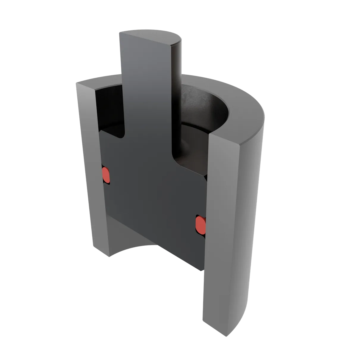
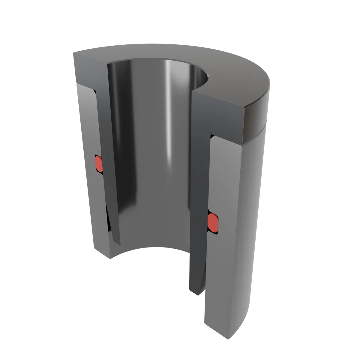
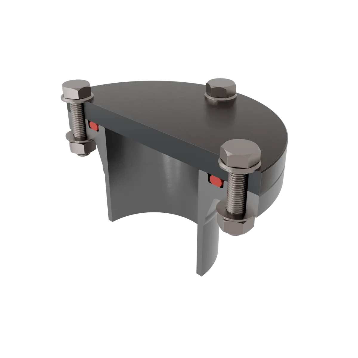
Flange sealing
Flange seals are characterised by very good axial accessibility of the installation space. Here, hardly any stretching is required for installation. Nevertheless, attention is needed: with the flange seal, there is a particularly high risk that the cover is not initially seated correctly during installation, thereby leading to pinching of the O-ring.
Piston seal
Just like the rod seal, the piston seal consists of an O-ring with a radial installation direction. In the piston seal, the installation groove is located in the inner part, the piston. The O-ring must be stretched in order to insert it into the groove.
An expanding sleeve is used to produce the necessary stretching without causing permanent damage. In addition, a sufficiently long guide should be provided when the piston with the O-ring is inserted into the cylinder. This ensures the correct positioning of the two components and rules out pinching.
Rod seal
In the rod seal, the installation space is located in the outer part, the cylinder. Installation personnel must deform the O-ring in order to bring it into its final position. To do this, the O-ring should be compressed into a kidney-like shape. Once the installation space is reached, the O-ring snaps into place. For sufficiently elastic seals, manual compression is unproblematic.
Less flexible O-rings should be brought into the kidney shape using an installation aid. These ensure that the O-rings are not bent too strongly at any one point.
Optimal installation for the different groove shapes
When designing the installation space, designers can draw on different groove shapes. They deviate from the standard case, the rectangular groove, when technical reasons require this at a specific point. Only special cases justify the use of more elaborate and therefore more expensive groove shapes. You can find the basics of design under O-ring grooves and in the O-ring groove calculation.
Recommended groove width (NB) and groove depth (NT) per cord thickness, separated by sealing type and static or dynamic application. All dimensions in millimetres, guide values for the design.
| Cord thickness mm | Flange seal | Piston seal | Rod seal | |||||||
|---|---|---|---|---|---|---|---|---|---|---|
| static | static | dynamic | static | dynamic | ||||||
| NB | NT | NB | NT | NB | NT | NB | NT | NB | NT | |
| 1.00 | 1.90 | 0.70 | 1.58 | 0.70 | 1.58 | 0.85 | 1.58 | 0.70 | 1.58 | 0.85 |
| 1.50 | 2.80 | 1.10 | 2.19 | 1.05 | 2.19 | 1.27 | 2.19 | 1.05 | 2.19 | 1.27 |
| 1.78 | 3.20 | 1.30 | 2.53 | 1.30 | 2.53 | 1.50 | 2.53 | 1.30 | 2.53 | 1.50 |
| 2.00 | 3.40 | 1.50 | 2.78 | 1.50 | 2.78 | 1.65 | 2.78 | 1.50 | 2.78 | 1.65 |
| 2.50 | 3.90 | 1.90 | 3.37 | 1.90 | 3.37 | 2.12 | 3.37 | 1.90 | 3.37 | 2.12 |
| 2.62 | 4.00 | 2.00 | 3.51 | 2.00 | 3.51 | 2.22 | 3.51 | 2.00 | 3.51 | 2.22 |
| 3.00 | 4.60 | 2.30 | 3.98 | 2.30 | 3.98 | 2.55 | 3.98 | 2.30 | 3.98 | 2.55 |
| 3.53 | 5.30 | 2.70 | 4.67 | 2.70 | 4.67 | 2.95 | 4.67 | 2.70 | 4.67 | 2.95 |
| 4.00 | 6.00 | 3.10 | 5.23 | 3.10 | 5.23 | 3.30 | 5.23 | 3.10 | 5.23 | 3.30 |
| 4.50 | 6.50 | 3.50 | 5.90 | 3.50 | 5.90 | 3.80 | 5.90 | 3.50 | 5.90 | 3.80 |
| 5.00 | 7.40 | 3.90 | 6.48 | 3.90 | 6.48 | 4.30 | 6.48 | 3.90 | 6.48 | 4.30 |
| 5.33 | 7.60 | 4.20 | 6.86 | 4.20 | 6.86 | 4.60 | 6.86 | 4.20 | 6.86 | 4.60 |
| 5.50 | 7.60 | 4.40 | 7.05 | 4.40 | 7.05 | 4.80 | 7.05 | 4.40 | 7.05 | 4.80 |
| 6.00 | 8.00 | 4.80 | 7.59 | 4.80 | 7.59 | 5.20 | 7.59 | 4.80 | 7.59 | 5.20 |
| 7.00 | 8.70 | 5.70 | 8.68 | 5.80 | 8.68 | 6.00 | 8.68 | 5.80 | 8.68 | 6.00 |
| 8.00 | 9.80 | 6.70 | 9.88 | 6.80 | 9.88 | 7.00 | 9.88 | 6.80 | 9.88 | 7.00 |
| 9.00 | 11.20 | 7.60 | 11.14 | 7.70 | 11.14 | 7.90 | 11.14 | 7.70 | 11.14 | 7.90 |
| 10.00 | 12.20 | 8.60 | 12.38 | 8.60 | 12.38 | 8.80 | 12.38 | 8.60 | 12.38 | 8.80 |
NB Groove width · NT Groove depth · all values in mm. Guide values for groove design; the decisive factors are material, tolerances and operating conditions. Check dimensions with our O-ring groove calculation.

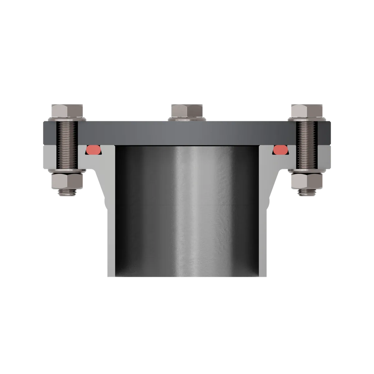
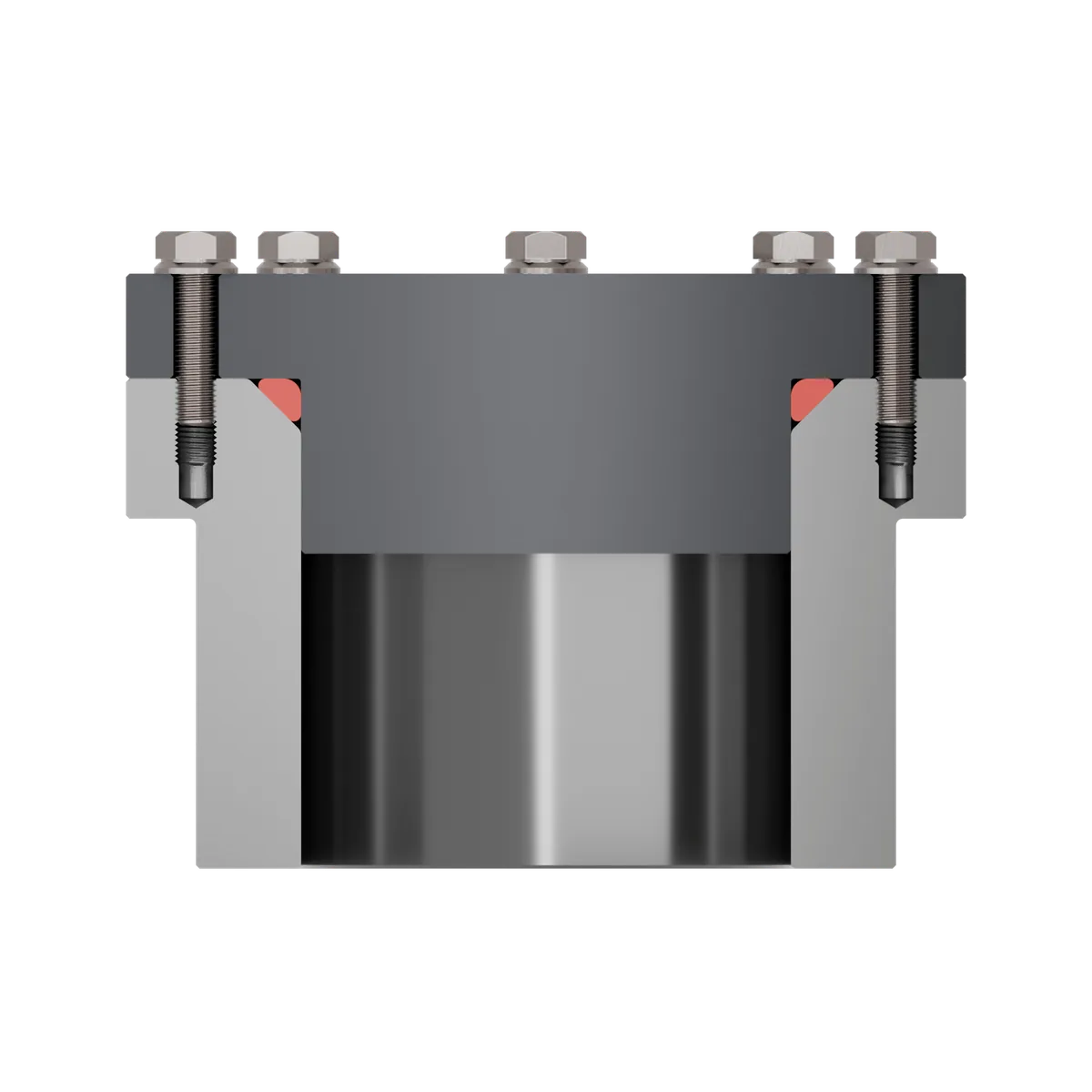
Rectangular groove
The rectangular groove is the predominant installation space for piston, rod and flange seals. As a basic requirement for installation, all groove edges must be provided with sufficient radii. This also includes clean surfaces and sufficient lead-in chamfers. For pressurised applications, there is an additional consideration: the O-ring must rest against the flank of the groove facing away from the pressure in order to prevent migration.
Trapezoidal groove
The trapezoidal groove, also known as a dovetail groove, is shaped so that the groove holds the O-ring in a defined position. This makes the installation process and also maintenance easier. It can also be useful during operation, for example when machines or tools open and close regularly at the sealing point.
The upper edge of the groove must be provided with a sufficiently large radius so that the O-ring is not damaged during installation. The same applies to the half trapezoidal groove, in which only one flank of the groove holds the O-ring.
Triangular groove
A triangular groove is an alternative for implementing flange seals. In this case, the O-ring rests against three contact faces in the compressed state. The sealing function depends heavily on the precise execution of the groove. Particular care must be taken here to ensure that the O-ring rests cleanly and is not pinched by the cover.
Consider the material properties
It is not only the type of seal and the groove shape that dictate the correct approach. The special properties of the respective sealing material must also be taken into account. While most O-ring materials are elastic, there are also materials that can only be reversibly deformed to a very limited extent.
This applies above all to O-rings made of PTFE. Stretching, compressing or kinking must be strictly avoided. FEP O-rings are somewhat less critical than the rigid PTFE O-rings, yet their installation requires particular care. They consist of a rubber core encapsulated in plastic. If the protective jacket is overstretched during installation, cracks occur. As a result, the more vulnerable core is exposed to media attack.
Choosing the right lubricant
Lubricants are a key aid for making installation easier. They reduce friction and can thus make installation more efficient and safer. In addition, they extend service life by permanently lowering friction in dynamic applications.
When making the selection, media compatibility should be the decisive factor above all:
| Material | Lubricant | Note |
|---|---|---|
| VMQ (silicone) | Avoid silicone-based | Silicone-based lubricants attack silicone. |
| NBR | Silicone base suitable | Improved protection against weathering. |
| EPDM | Avoid mineral oil base | EPDM is not resistant to mineral oil. |
An alternative to silicone are lubricants based on mineral oil. However, the pairing with the non-mineral-oil-resistant sealing material EPDM must be strictly avoided. You can read about how the choice of lubricant affects ageing and what to look out for between uses under Storage of O-rings.
Conclusion on O-ring installation
Installation plays a key role in preventing premature damage. On the one hand, the installation process serves to check the preparation of the installation space. Installation may only take place if the machining of the groove meets the specifications.
On the other hand, the installation itself should be carried out using suitable aids and with great care, so that satisfactory service lives are achieved.
Frequently asked questions
How much may I stretch an O-ring during installation?
Which lubricant is suitable for O-ring installation?
What must I pay attention to when installing PTFE and FEP O-rings?
What installation aids are there?
Why does an O-ring fail shortly after installation?