
O-rings: function, materials and selection
O-rings look simple, but their reliable function is the sum of material selection, dimensions, installation space, assembly and storage. This guide takes you through every step of the design.

- An O-ring is an elastic sealing element with a round cross-section. The sealing effect is created by the compression of the cross-section in the groove.
- The design covers three axes: mechanical properties, media resistance and temperature resistance. Only the specific material compound is decisive.
- Standardised sizes to ISO 3601, AS568 or DIN 3771 ensure quality, price and availability.
- For compression, 15 to 30 percent applies to static seals and a maximum of 20 percent to dynamic seals.
- Most failures are caused by media, temperature, physical stress, assembly or storage, and can be avoided through sound design.
What is an O-ring?
An O-ring is a circular sealing element with a round cross-section that can deform elastically. It is defined by exactly two features: the round profile cross-section and the elasticity. Both distinguish the O-ring from other sealing elements.
The elasticity relates above all to the cross-section. In the installed state, the cross-section must undergo a defined elastic deformation for a sealing effect to arise. Two components meet, each with one face, with the O-ring in between. The component dimensions generate a compressive force that squeezes the cross-section.
The O-ring seals two spaces against each other or against the environment. If it fails, process media or lubricants escape, or air enters a vacuum and contaminates the system. Sound design covers material selection, dimensions and the layout of the installation space. Assembly, failure analysis and storage follow.
Functional principle of the sealing effect
The inner sealing face, the O-ring and the outer sealing face must be positioned precisely relative to one another. The degree of deformation, that is the percentage change in the cross-section, is called compression. Through the deformation, the material conforms to fine surface flaws such as those created during turning or milling, and closes them.
A clear example is the pairing of piston and cylinder, for instance in a combustion engine, in pneumatics or in hydraulics. In a pneumatic cylinder, lubricating oil reduces friction while air transmits the force. Deep longitudinal scoring in the cylinder running surface means the O-ring can no longer compensate for it, and the system leaks.
The installation space for the O-ring is the O-ring groove. It runs in a full circle through one of the components. During assembly, the O-ring is inserted from the front or snapped into the groove under stretching or compression. In operation, only the portion of the cross-section that projects beyond the groove is deformed.
Distinction from other sealing elements
The round cross-section and the elasticity clearly distinguish the O-ring from other sealing elements.
Flat gasket
The flat gasket has a rectangular cross-section and is likewise compressed for flange connections. The starting material is flat sheet, often cut to shape by laser cutting. Paper and fibre materials are also possible. This produces round, rectangular and irregular contours.
Profile seal
Profile seals include lip seals, U- and D-profile seals as well as hollow-chamber profile seals. They are usually produced as continuous material, for example for doors and windows or for sound and thermal insulation, and are mostly installed loosely butted.
Manufacturing and processes
An O-ring cannot be cut out of flat material, because the round cross-section would be lost in the process. Ideally it is produced without a seam. For standard O-rings in high volumes, two main processes are used.
Common to all processes is vulcanization. Under heat the elastic properties develop, and rubbers become elastomers. The molecules cross-link strongly and spring back after being relieved of load.
Dimensions, standards and size tables
An O-ring is described by two dimensions: the diameter of the ring and the diameter of the circular cross-section. The latter is called cord thickness, abbreviated CS. The nominal dimension is the inner diameter, abbreviated ID. The size designation follows the scheme "ID x CS". For an order, material, tolerances and quality requirements are added. Standardised size tables are part of the national and international O-ring standards.
The most important standards at a glance
| Standard | Measurement system | Characteristics |
|---|---|---|
| AS568 | imperial | Globally dominant standard, originally an aerospace standard. Sequential numbering of the ID and CS combinations. Converted cord thicknesses from 1.02 to 6.99 mm, maximum inner diameter around 660 mm. |
| BS 1806 | imperial | British standard. Defines sizes between the steps of AS568. |
| DIN 3771 | metric | German standard and the metric counterpart to AS568. Also defines tolerances, quality properties and the design of the installation space. |
| ISO 3601 | metric and imperial | International standard that brings together imperial and metric dimensions. It has largely replaced DIN 3771 and many national standards, and additionally defines minimum requirements for common rubber materials. |
In practice, the standard helps to find the right size for a given installation space, or conversely to design the installation space for a fixed size. Existing installation spaces can thus be reworked.
Advantages of standardised sizes
Standardised sizes affect three factors in purchasing:
- Quality: The reference to a standard proves that requirements are met, and high-volume production runs with stable process controls.
- Price: High demand and transparency allow price comparisons and thus higher-quality materials without multiplying the cost.
- Availability: Standard sizes are usually in stock, and even special material grades are available at short notice.
Requirements for the material
Before a material is chosen, the requirements should be clarified along three axes: mechanical, chemical and thermal.
The most important materials
The following overview classifies the common O-ring materials by temperature resistance, chemical resistance and elasticity. The values are guide values. For the specific design, the data sheets and resistance lists of the respective material apply.
| Material | Temperature resistance | Chemical resistance | Elasticity |
|---|---|---|---|
| FFKM (ECOLAST) | −20/+270 °C, special types up to +340 °C | high | high |
| FEP-encapsulated | −60/+205 °C | high | medium |
| FKM | −25/+200 °C | medium | high |
| PTFE | −250/+250 °C | high | low |
| NBR | −30/+120 °C | low | high |
| HNBR | −30/+150 °C | medium | high |
| EPDM | −45/+150 °C | medium | high |
| Silicone (VMQ) | −60/+200 °C | low | high |
| FVMQ | −60/+200 °C | medium | high |
| FEPM | −10/+200 °C | medium | high |
The most important materials in detail
FFKM is chemically highly resistant, and almost no chemical attacks it. It is a fully fluorinated elastomer, a perfluoroelastomer, and very cost-intensive. NH O-RING offers FFKM under its own brand ECOLAST with operating temperatures up to +270 °C in the standard grade and up to +340 °C in high-temperature compounds. Well-known trade names from other manufacturers are Kalrez and Simriz. More on this in the article FFKM O-rings.
FKM is likewise a fluorinated elastomer, but with a lower fluorine content. The maximum operating temperature is +200 °C, the elasticity is higher and the cost level lower than with FFKM. FKM is also called FPM or Viton. Details in the article FKM O-rings.
VMQ (silicone) is very pure, transparent and low in reactivity, harmless to health as well as odourless and tasteless. This predestines the material for medical and food technology. Its weaknesses are the high mechanical abrasion and the low stretchability.
EPDM is the alternative to FKM for hot water and steam, for example in heating and sanitary applications or in steam sterilization. It is food-safe and abrasion-resistant. Trade names are Keltan, Vistalon and Nordel.
NBR is weak with steam, but offers very good mechanical properties with high tear and abrasion resistance. Ozone attacks NBR, so it does not belong outdoors unless ozone-protection compounds are used. The heat resistance is around 100 °C. Brand names are Perbunan and Europrene.
Properties in comparison
| Property | FFKM | FKM | VMQ | EPDM | NBR |
|---|---|---|---|---|---|
| Abrasion resistance | good | good | adequate | good | good |
| Compression set | excellent | very good | good | good | very good |
| Ozone resistance | excellent | very good | very good | good | poor |
| Oil and grease resistance | excellent | very good | adequate | poor | good |
Material blends and compounds
An O-ring material is never the pure base elastomer. Added to it are additives in small quantities and fillers in higher concentration, which also serve to reduce cost. This is how many compounds with different properties are created from one base elastomer. Which media a material can withstand can only be clarified via detailed resistance lists, which comprise several hundred substances per material. You will find the tool for this at Media resistances.
Flange, piston and rod seal
Seals are first distinguished by whether they work statically or dynamically. A static seal remains stationary and is the standard case. A dynamic seal moves in operation and is more critical. Three typical designs result from the installation situation.
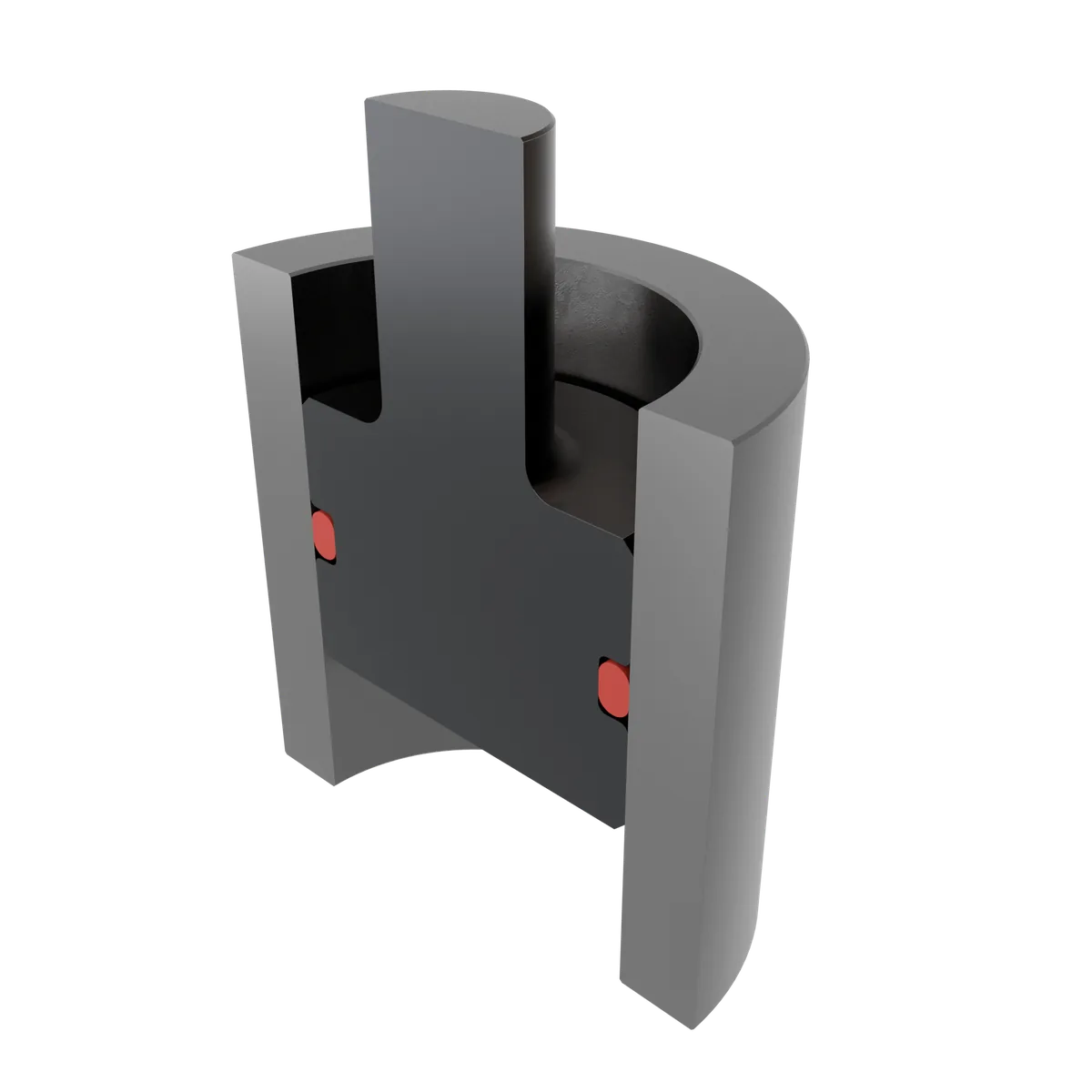
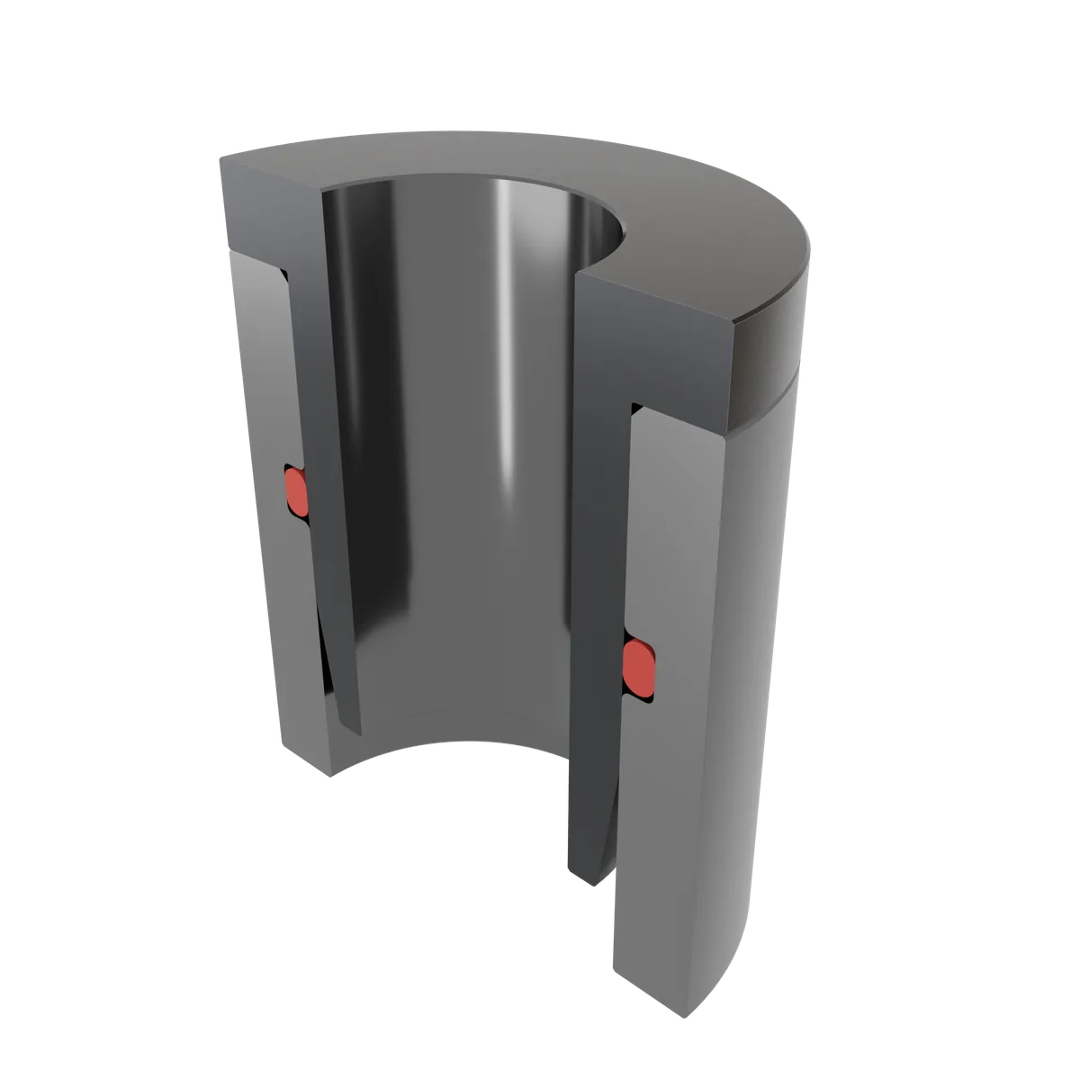
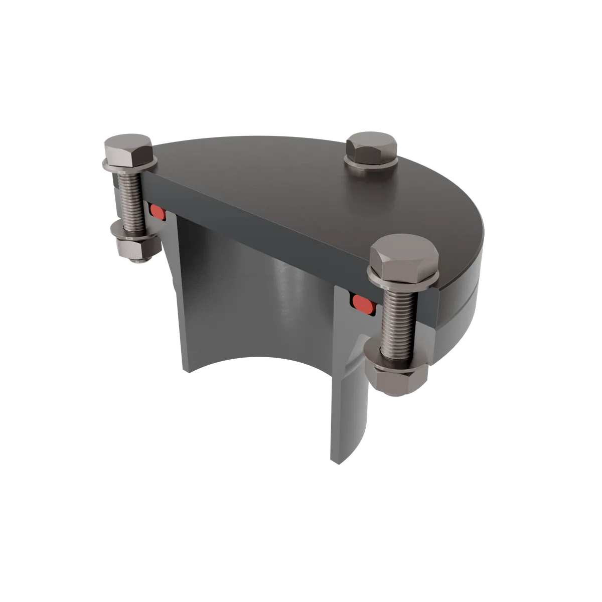
Groove shapes and groove geometry
The installation space is a decisive factor in the function. Three groove shapes occur in practice.
Groove width and groove depth per cord thickness for flange, piston and rod seals, static and dynamic.
To the O-ring groove dimension table →
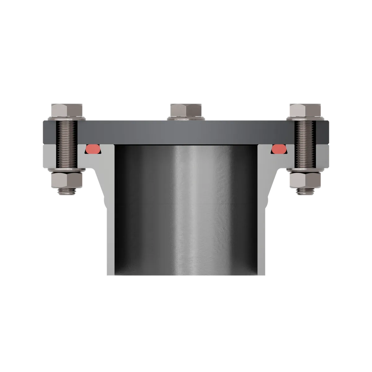
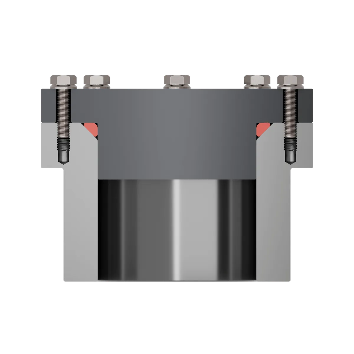
- Rectangular groove: the simplest and most economical shape. The flanks are at right angles to the groove base, and it is easy to produce by turning.
- Trapezoidal groove (dovetail groove): the flanks converge towards the top and fix the O-ring in place. Good for frequent opening, but with higher manufacturing costs.
- Triangular groove: for flange connections, the O-ring is compressed between three contact faces. The target values are hard to maintain, the swelling space is small and the tolerances are demanding. Therefore only for special cases.
Relevant dimensions for the groove geometry
Cord diameter, sealing gap and groove depth together determine the compression. The following values serve as guidance:
| Parameter | Recommendation |
|---|---|
| Groove depth | less than the cord thickness |
| Compression, static seal | 15 to 30 percent |
| Compression, dynamic seal | maximum 20 percent |
| Groove fill | about 85 percent of the groove in the compressed state |
| Angle of the groove flanks | increase by a maximum of 5 degrees |
The groove width must be at least equal to the cord thickness; in practice it is made larger to allow for swelling behaviour. A groove that is too wide is harmful under fluctuating pressure, because the O-ring migrates and generates friction. In addition, all contact and overrun edges should be rounded and lead-in chamfers provided.
The stick-slip effect, that is the jerky sliding at the transition from static to sliding friction, can be avoided with friction-optimised O-rings and a suitable balance of compression and groove depth. For the specific design, the O-ring groove calculation.
The most important approvals
Different approvals are required depending on the application. The most important ones by field of use:
Food
- FDA (Food and Drug Administration, USA), applied worldwide.
- 3-A Sanitary Standards, also for pharmaceuticals, with testing of the extraction behaviour with high-fat dairy products.
Pharmaceuticals and medicine
- USP, the US Pharmacopeia, classifies materials into six classes of biocompatibility.
- ADI-free (free of Animal Derived Ingredients) supplements the FDA and rules out BSE or TSE transmission.
Drinking water
- In Germany, the Elastomer Guideline (KTW) with testing for changes in odour and taste, visual influence and extraction.
- DVGW W270 (German Technical and Scientific Association for Gas and Water) tests the growth of microorganisms.
- The following apply internationally: WRAS (United Kingdom), NSF61 (USA) and the ÖNORM (Austria).
Gas
- In Germany, DIN EN 549 or DIN EN 682.
- NORSOK M-710 from the Norwegian oil and gas industry, for pressure peaks and wide temperature ranges.
Avoiding causes of failure
Damage to O-rings can be assigned to four categories. Anyone who knows the mechanisms can avoid them during the design.
Media exposure
Two mechanisms are at work here. In the case of swelling, components of the medium penetrate the material, the volume increases, compression and friction rise, and the O-ring can be forced out of the groove. In the case of extraction, the medium dissolves components out, the volume decreases, the compression falls below the minimum and leakage occurs, first where the initial compression was lowest. Materials with a high plasticizer content are particularly at risk.
A chemical attack can lead to chain scission or post-cross-linking. Signs are a softened or sticky surface, a brittle, cracked surface, or a strong increase or decrease in volume. The assembly medium also counts: EPDM does not tolerate mineral-oil-based substances, and silicone oil attacks VMQ.
Temperature and ageing
Higher temperatures accelerate the chemical processes and shorten the service life. Post-cross-linking makes the material harder, chain scission reduces the bonds, and both lower the flexibility. Signs of overheating are surface cracking, shiny spots, embrittlement and permanent deformation. A larger cord thickness provides reserve. Cold only causes a temporary loss of elasticity, which is fully reversible after warming up.
During ageing, UV light leads to deep cracks via a higher ozone concentration. NBR in particular is affected, while EPDM and FKM are unproblematic. Ozone-protected formulations, stress-free storage and protection against air exchange provide a remedy.
Physical stress
Pressure and friction stress the O-ring, and damage often occurs as early as during assembly, for example through stretching in the piston seal or compression in the rod seal. Sharp edges create cuts or shearing and thus predetermined breaking points.
- Gap extrusion: The pressure forces the O-ring against the groove flank facing away from the pressure and into the sealing gap, and the material is sheared over the groove edge. Avoid this with a small sealing gap, firmer O-rings and a back-up ring made of extrusion-resistant material.
- Explosive decompression: Gas penetrates the material under pressure; when the pressure suddenly drops, it expands and creates blisters and cracks. Avoid this by preventing pressure surges, longer pressure-release times, a high hardness with low gas permeability, and a design to NORSOK M-710.
Manufacturing defects
Under-vulcanization with insufficient cross-linking leads to a high compression set and inadequate elasticity. Crack formation can arise from contaminated tools, insufficiently mixed compounds, and during demoulding and post-processing. Incoming goods inspections and reliable suppliers prevent this.
Several routine tests serve for quality control: the density test distinguishes materials, the hardness test measures the hardness, which is usually between 60 and 90 Shore A, the dimensional test is carried out with a measuring cone or measuring machine, and the compression set reveals formulation variations and processing errors.
Safe assembly
Typical damage patterns arise during assembly. When twisting, too much friction creates local overstretching with cracks; assembly oils and greases provide a remedy. Overstretching depends on the tear strength; an assembly cone helps. Pinching results from imprecise positioning against an edge; lead-in chamfers prevent it. Useful aids are an expander sleeve for the piston seal and assembly pliers for the rod seal.
Five tips for safe assembly
- Use a suitable assembly grease or oil to reduce friction.
- Ensure a clean and burr-free installation space so that the O-ring suffers no mechanical damage and the system is not contaminated.
- Support safe assembly with adequate lead-in chamfers and a high surface finish.
- Do not twist or overstretch the O-ring, because this can cause permanent damage.
- Take the material properties into account to safeguard the pairing of O-ring material and assembly grease and not to exceed the permissible elongation.
Storage in accordance with standards
Storage in accordance with standards preserves the properties of the O-ring. Pressure loading is to be avoided, draughts and sunlight should be limited, and a dark, enclosed room is ideal. Temperature peaks are to be moderated, and before assembly O-rings are warmed to room temperature.
The maximum storage time depends on the material. The following values apply to the O-rings from NH O-RING:
| Material | Maximum storage time |
|---|---|
| FKM | 10 years |
| FFKM (ECOLAST) | 15 years |
| FEP-encapsulated | 15 years |
| PTFE | practically unlimited |
A proven storage concept relies on one storage room per site, storage by single type, and keeping the O-rings in their original packaging, for example airtight PE film bags, from which the O-rings are only removed at assembly. Demand-based purchasing keeps the stock small.
Frequently asked questions
How is the size of an O-ring specified?
Which compression is correct?
Which material suits my application?
What does the compression set mean?
What is gap extrusion and how can it be avoided?
How long can O-rings be stored?
What matters during assembly?
