
Flange seal: material and design
In a flange seal, the O-ring sits in an axial groove between two faces and is compressed when the flanges are bolted together. We explain step by step what matters for material, groove design, pressure direction and assembly.

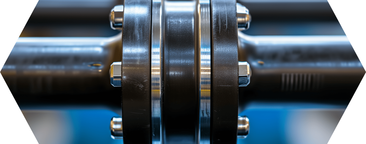
- The flange seal with an O-ring is a static seal: the ring sits in an axial groove and is compressed when the flanges are bolted together.
- Material selection by medium, temperature and pressure: FKM as the standard, FFKM for aggressive media and high temperatures, EPDM for hot water and steam, PTFE for the widest chemical resistance.
- The groove depth sets the compression and limits it as soon as the faces lie flat against each other. This protects the O-ring from overloading.
- Tighten the bolts crosswise and with a torque wrench; the sealing faces must be flat and clean.
- Available from NH O-RING from stock and with no minimum order quantity, in FKM, FFKM ECOLAST, EPDM and PTFE.
Flange seal with an O-ring: the principle
A flange seal sits between two flat faces and prevents liquids or gases from escaping at the joint. It is therefore a key component in piping, pumps, valves and housings. Flat gaskets are the traditional choice. In many applications, however, the O-ring is the more compact and more reliable solution.
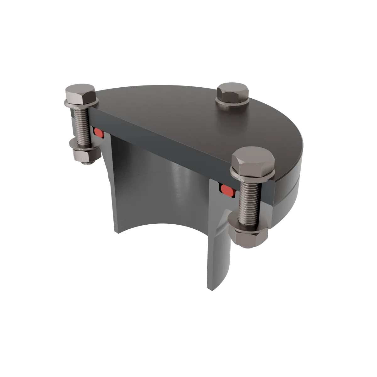
With an O-ring as a flange seal, the ring sits in a groove machined into one of the two faces. When the flanges are bolted together, the faces are drawn together and the O-ring is compressed axially. This compression creates the sealing effect. It is a static seal, because the faces do not move relative to each other during operation.
The advantage over the flat gasket lies in the defined geometry. The O-ring is positioned precisely by the groove and compressed to a fixed dimension. Overloading due to excessive tightening torque is limited by design as soon as the faces lie flat against each other.
Compression, pressure direction and installation position
In the axial flange seal, the O-ring is compressed perpendicular to the groove base. For static applications, the compression is usually higher than for dynamic seals, because there is no friction or wear from movement to take into account. Too little compression does not seal reliably, while too much stresses the material unnecessarily.
Pressure from inside or outside
The pressure direction determines which flank of the groove the O-ring is pushed against. If the pressure acts from the inside outward, the ring is pressed against the outer groove flank. If the pressure acts from the outside, against the inner flank. In both cases, the groove must be designed so that the O-ring sits securely and is not pushed into the sealing gap.
Check the installation position
At high pressures, the O-ring can extrude into the gap between the flange faces. Countermeasures are a narrow gap, a harder material or back-up rings. The exact design of groove width, groove depth and permissible gap is best carried out with the O-ring groove calculation.
Materials for O-ring flange seals
The material determines resistance, temperature range and sealing behaviour. The decisive factors are the medium to be sealed, the operating temperature and the pressure. The following overview classifies the common materials for O-ring flange seals.
| Material | Operating temperature | Resistance | Use as a flange seal |
|---|---|---|---|
| FKM | −25/+200 °C, extremes up to +225 °C | Oils, fuels, many chemicals | Proven standard for most industrial flange joints. |
| FFKM (ECOLAST) | −20/+270 °C, types up to +330 °C | almost all media | When the medium and temperature exceed FKM, for example in the chemical and semiconductor industries. |
| PTFE | −250/+250 °C | almost universal chemical resistance | For aggressive media. Hard and not elastic, flows under sustained load. |
| EPDM | depending on compound | Water, steam, glycols, many acids and alkalis | For hot water, steam and sanitary applications. Not resistant to mineral oils. |
Elastomers and plastics compared
FKM is the most widely used material and covers a large share of applications involving oils, fuels and chemicals. When FKM reaches its limits, for example with very aggressive media or high temperatures, FFKM from our own ECOLAST brand is used. It is almost universally resistant and, depending on the type, can be used up to +330 °C.
For hot water, steam and sanitary applications, EPDM O-rings are the right choice. EPDM is, however, not resistant to mineral oils and fuels. Where the widest chemical resistance matters and elasticity is secondary, PTFE O-rings are used. PTFE is hard and not elastic and tends to flow under sustained load, which is why the compression must be limited carefully.
Groove design for the axial flange seal
The groove holds the O-ring and sets its compression. In the axial flange seal, the groove is a continuous rectangular groove in one of the two faces. Three dimensions are decisive.
Recommended groove width (NB) and groove depth (NT) per cord thickness, separated by type of sealing and static or dynamic use. All dimensions in millimetres, guide values for the design.
| Cord thickness mm | Flange seal | Piston seal | Rod seal | |||||||
|---|---|---|---|---|---|---|---|---|---|---|
| static | static | dynamic | static | dynamic | ||||||
| NB | NT | NB | NT | NB | NT | NB | NT | NB | NT | |
| 1.00 | 1.90 | 0.70 | 1.58 | 0.70 | 1.58 | 0.85 | 1.58 | 0.70 | 1.58 | 0.85 |
| 1.50 | 2.80 | 1.10 | 2.19 | 1.05 | 2.19 | 1.27 | 2.19 | 1.05 | 2.19 | 1.27 |
| 1.78 | 3.20 | 1.30 | 2.53 | 1.30 | 2.53 | 1.50 | 2.53 | 1.30 | 2.53 | 1.50 |
| 2.00 | 3.40 | 1.50 | 2.78 | 1.50 | 2.78 | 1.65 | 2.78 | 1.50 | 2.78 | 1.65 |
| 2.50 | 3.90 | 1.90 | 3.37 | 1.90 | 3.37 | 2.12 | 3.37 | 1.90 | 3.37 | 2.12 |
| 2.62 | 4.00 | 2.00 | 3.51 | 2.00 | 3.51 | 2.22 | 3.51 | 2.00 | 3.51 | 2.22 |
| 3.00 | 4.60 | 2.30 | 3.98 | 2.30 | 3.98 | 2.55 | 3.98 | 2.30 | 3.98 | 2.55 |
| 3.53 | 5.30 | 2.70 | 4.67 | 2.70 | 4.67 | 2.95 | 4.67 | 2.70 | 4.67 | 2.95 |
| 4.00 | 6.00 | 3.10 | 5.23 | 3.10 | 5.23 | 3.30 | 5.23 | 3.10 | 5.23 | 3.30 |
| 4.50 | 6.50 | 3.50 | 5.90 | 3.50 | 5.90 | 3.80 | 5.90 | 3.50 | 5.90 | 3.80 |
| 5.00 | 7.40 | 3.90 | 6.48 | 3.90 | 6.48 | 4.30 | 6.48 | 3.90 | 6.48 | 4.30 |
| 5.33 | 7.60 | 4.20 | 6.86 | 4.20 | 6.86 | 4.60 | 6.86 | 4.20 | 6.86 | 4.60 |
| 5.50 | 7.60 | 4.40 | 7.05 | 4.40 | 7.05 | 4.80 | 7.05 | 4.40 | 7.05 | 4.80 |
| 6.00 | 8.00 | 4.80 | 7.59 | 4.80 | 7.59 | 5.20 | 7.59 | 4.80 | 7.59 | 5.20 |
| 7.00 | 8.70 | 5.70 | 8.68 | 5.80 | 8.68 | 6.00 | 8.68 | 5.80 | 8.68 | 6.00 |
| 8.00 | 9.80 | 6.70 | 9.88 | 6.80 | 9.88 | 7.00 | 9.88 | 6.80 | 9.88 | 7.00 |
| 9.00 | 11.20 | 7.60 | 11.14 | 7.70 | 11.14 | 7.90 | 11.14 | 7.70 | 11.14 | 7.90 |
| 10.00 | 12.20 | 8.60 | 12.38 | 8.60 | 12.38 | 8.80 | 12.38 | 8.60 | 12.38 | 8.80 |
NB groove width · NT groove depth · all values in mm. Guide values for groove design; the decisive factors are material, tolerances and operating conditions. Check dimensions with our O-ring groove calculation.
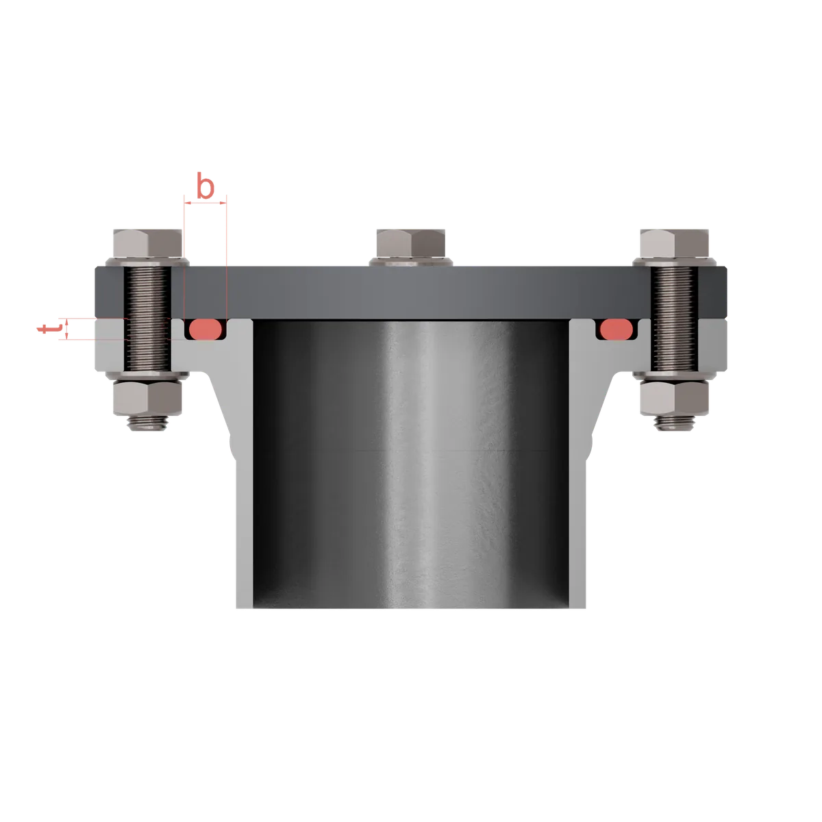
- Groove depth: determines the compression. It is smaller than the cord thickness of the O-ring, so that the ring is compressed by a defined amount when the flanges are bolted together.
- Groove width: must accommodate the compressed ring. The O-ring spreads out under compression and requires a fill level that avoids completely filling the groove.
- Edge radii and surface: sharp edges damage the ring during assembly. The sealing faces need a sufficient surface finish so that no leakage paths form.
The exact dimensions depend on cord thickness, material and pressure. The O-ring groove calculation gives you the right groove dimensions for your cord thickness. O-rings react more sensitively to groove dimensions and surface finish than flat gaskets, but with correct design they provide very reliable sealing in a small installation space.
Assembly of the flange joint
Even the best seal fails if it is fitted incorrectly. A few basic rules apply to the O-ring as a flange seal.
Tighten crosswise
The bolts are tightened crosswise so that the pressure is distributed evenly across the entire seal. A proven sequence starts at 12 o'clock, then 6 o'clock, then 3 o'clock and 9 o'clock, and continues in this pattern until all bolts are seated.
Work with torque
A torque wrench ensures that each bolt is tightened to the specified torque. The following values are guide values for common bolt sizes. The specifications of the bolt and seal manufacturer and the operating conditions remain decisive.
| Bolt size | Steel bolts | Stainless steel bolts |
|---|---|---|
| M8 | 20-25 Nm | 15-20 Nm |
| M10 | 40-50 Nm | 30-40 Nm |
| M12 | 70-85 Nm | 55-70 Nm |
| M16 | 160-200 Nm | 120-160 Nm |
| M20 | 300-350 Nm | 230-280 Nm |
| M24 | 450-500 Nm | 340-380 Nm |
| M30 | 800-900 Nm | 600-700 Nm |
With the O-ring flange seal, the compression is limited by the groove depth as soon as the faces lie flat against each other. This protects the ring from overloading. Clean and flat flange faces are a prerequisite for the ring to sit evenly all the way around.
O-ring or flat gasket?
Both designs have their place. The choice depends on installation space, pressure, temperature and medium.
The O-ring excels at
- compact installation spaces and complex-shaped sealing faces,
- defined compression via the groove, which limits overloading,
- simple assembly and low maintenance effort,
- reliable sealing across a wide pressure and temperature range.
The flat gasket excels at
- large flange joints with a large sealing face,
- compensating for unevenness in the flange faces,
- very high pressures and temperatures with metallic seals.
In return, the O-ring requires precise groove dimensions and a good surface finish and can be damaged by sharp edges. For many standard applications, it is the economical and reliable solution.
Fields of application
O-ring flange seals are found in a broad spectrum of industrial applications. A selection of typical fields.
We summarise which material suits which application under O-ring applications. Give us the medium, temperature and installation situation, and we will suggest the right material for you.
Frequently asked questions
What is a flange seal?
Which material is suitable for an O-ring flange seal?
How is the O-ring compressed in the flange seal?
How do you tighten a flange joint correctly?
O-ring or flat gasket, which is better?
Why does the O-ring extrude at high pressure?