
Designing a piston seal with O-rings
How an O-ring reliably seals a piston: radial compression, the correct groove arrangement, static and dynamic application, material selection and assembly. Explained concisely and in practical terms.

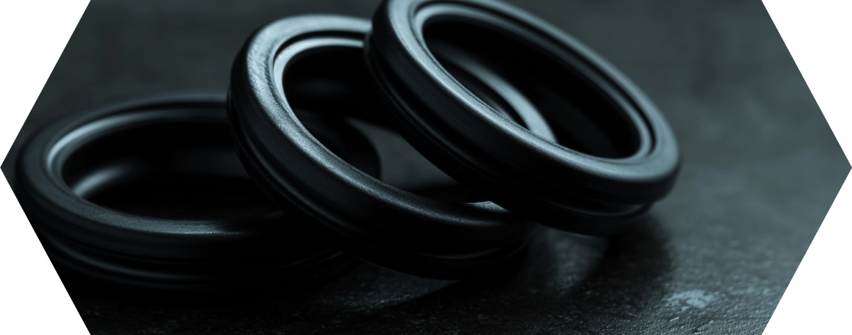
- A piston seal separates two pressure chambers in the cylinder and holds the pressure at the piston.
- The O-ring seals through radial compression; the system pressure increases the contact force.
- With a piston seal, the groove sits in the piston and seals outward against the bore.
- For static sealing, the O-ring is almost always the right choice; dynamically at moderate pressure and stroke.
- Choose the material according to medium and temperature: NBR as the standard, FKM for higher requirements.
What a piston seal does
A piston seal separates two pressure chambers in a cylinder from one another. It prevents fluid or gas from flowing past the piston from the pressure side to the opposite side. This keeps the pressure where it is meant to act, and the movement of the piston remains controllable. Piston seals are therefore a central element in hydraulic and pneumatic systems.
An O-ring solves this task simply and robustly. The O-ring sits in a groove and seals against the opposing surface through radial compression. It needs no preferred direction and holds the pressure in both directions. Where you place the groove determines whether the O-ring seals outward or inward.
You can find more on the general range of applications of O-rings under O-ring applications.
Radial compression: how the O-ring seals
During installation, the O-ring is slightly compressed. This pre-compression creates an initial surface pressure at the groove base and the mating surface. As soon as system pressure is applied, it pushes the O-ring against the groove flank facing away from the pressure and additionally increases the contact force. The O-ring therefore seals more tightly the higher the pressure rises. This principle is called self-energizing.
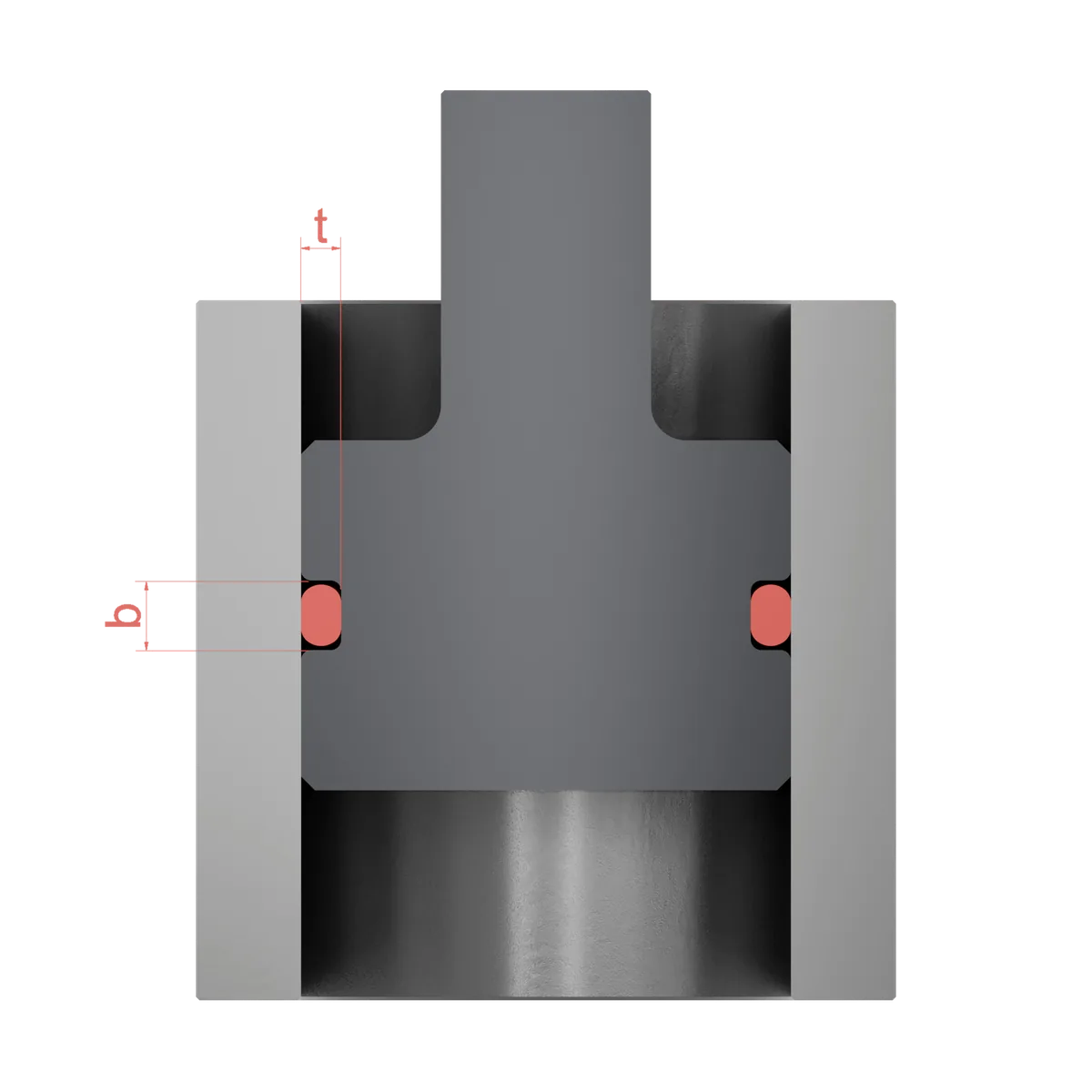
For the seal to work reliably, the compression and the gap to the mating surface must be in the right ratio. Too little compression leads to leakage, too much compression increases friction and wear. We explain the basics of the groove and its dimensions under O-ring grooves.
Groove in the piston or outward-sealing: the two arrangements
With a piston seal, the groove usually sits in the moving inner part, that is, in the piston. The O-ring then seals outward against the cylinder bore. This arrangement is called outward-sealing.
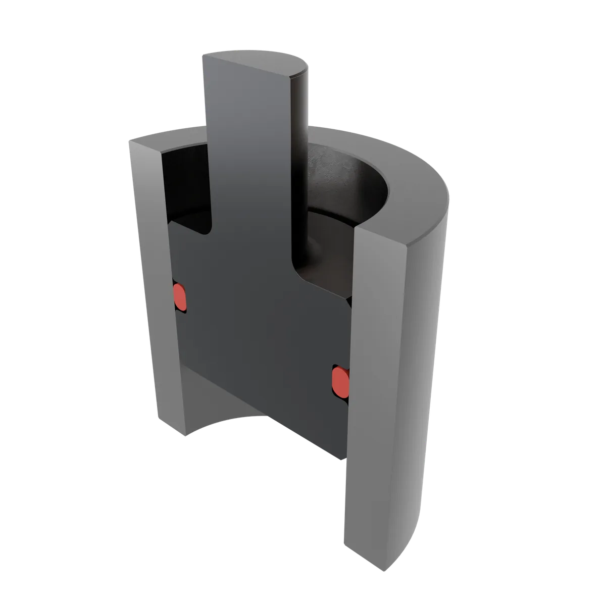
The opposite variant is the inward-sealing arrangement. Here the groove is located in the bore, and the O-ring seals inward against a through-going rod. This is the typical case of a rod seal.
The following applies to the piston seal: the decisive factors are the groove-base diameter at the piston and the diameter of the cylinder bore. From both, the compression and stretch of the O-ring result.
| Arrangement | Groove | Seals against | Typical case |
|---|---|---|---|
| Outward-sealing | in the piston | Cylinder bore | Piston seal |
| Inward-sealing | in the bore | Through-going rod | Rod seal |
Static or dynamic: the decisive difference
Whether an O-ring is suitable as a piston seal depends heavily on whether the sealing point is at rest or moving.
Static sealing: The sealing faces do not move against each other during operation. Here the O-ring is the simple and proven solution. Wear plays hardly any role; the design follows the standard values for the compression.
Dynamic sealing: The piston moves axially, the O-ring slides on the cylinder wall. Now friction, sliding speed, surface finish and wear matter. O-rings are suitable for slow and short stroke movements as well as for moderate pressures. At high speeds, long strokes or high pressures, profiled seals or back-up rings are usually used, often in combination with the O-ring as a preloading element.
Materials for piston seals
The material determines which medium, which temperature and which load the seal can withstand. For O-rings used as a piston seal, two elastomers are primarily relevant.
NBR (nitrile rubber): the standard for hydraulics and general applications with mineral oils and greases. Good abrasion resistance at a favourable price. Details under NBR O-rings.
FKM (fluoroelastomer): the choice for higher temperatures and more aggressive media. FKM75S covers a range of −25/+200 °C, the extreme grade FKMEX40 reaches from −40/+225 °C. More on this under FKM O-rings.
For very broad chemical resistance or temperatures up to +330 °C, the ECOLAST FFKM family offers suitable compounds. You select the right material according to medium, temperature and pressure.
| Material | Operating temperature | Suitability |
|---|---|---|
| NBR | depending on compound | Hydraulics, mineral oils, greases, standard |
| FKM75S | −25/+200 °C | higher temperatures, many media |
| FKMEX40 | −40/+225 °C | extended temperature range |
| FFKM (ECOLAST) | up to −15/+330 °C | widest resistance, high temperature |
Designing the groove correctly
The groove determines whether the seal works. Three dimensions are decisive for this:
Recommended groove width (NB) and groove depth (NT) per cord thickness, separated by type of sealing and static or dynamic use. All dimensions in millimetres, guide values for the design.
| Cord thickness mm | Flange seal | Piston seal | Rod seal | |||||||
|---|---|---|---|---|---|---|---|---|---|---|
| static | static | dynamic | static | dynamic | ||||||
| NB | NT | NB | NT | NB | NT | NB | NT | NB | NT | |
| 1.00 | 1.90 | 0.70 | 1.58 | 0.70 | 1.58 | 0.85 | 1.58 | 0.70 | 1.58 | 0.85 |
| 1.50 | 2.80 | 1.10 | 2.19 | 1.05 | 2.19 | 1.27 | 2.19 | 1.05 | 2.19 | 1.27 |
| 1.78 | 3.20 | 1.30 | 2.53 | 1.30 | 2.53 | 1.50 | 2.53 | 1.30 | 2.53 | 1.50 |
| 2.00 | 3.40 | 1.50 | 2.78 | 1.50 | 2.78 | 1.65 | 2.78 | 1.50 | 2.78 | 1.65 |
| 2.50 | 3.90 | 1.90 | 3.37 | 1.90 | 3.37 | 2.12 | 3.37 | 1.90 | 3.37 | 2.12 |
| 2.62 | 4.00 | 2.00 | 3.51 | 2.00 | 3.51 | 2.22 | 3.51 | 2.00 | 3.51 | 2.22 |
| 3.00 | 4.60 | 2.30 | 3.98 | 2.30 | 3.98 | 2.55 | 3.98 | 2.30 | 3.98 | 2.55 |
| 3.53 | 5.30 | 2.70 | 4.67 | 2.70 | 4.67 | 2.95 | 4.67 | 2.70 | 4.67 | 2.95 |
| 4.00 | 6.00 | 3.10 | 5.23 | 3.10 | 5.23 | 3.30 | 5.23 | 3.10 | 5.23 | 3.30 |
| 4.50 | 6.50 | 3.50 | 5.90 | 3.50 | 5.90 | 3.80 | 5.90 | 3.50 | 5.90 | 3.80 |
| 5.00 | 7.40 | 3.90 | 6.48 | 3.90 | 6.48 | 4.30 | 6.48 | 3.90 | 6.48 | 4.30 |
| 5.33 | 7.60 | 4.20 | 6.86 | 4.20 | 6.86 | 4.60 | 6.86 | 4.20 | 6.86 | 4.60 |
| 5.50 | 7.60 | 4.40 | 7.05 | 4.40 | 7.05 | 4.80 | 7.05 | 4.40 | 7.05 | 4.80 |
| 6.00 | 8.00 | 4.80 | 7.59 | 4.80 | 7.59 | 5.20 | 7.59 | 4.80 | 7.59 | 5.20 |
| 7.00 | 8.70 | 5.70 | 8.68 | 5.80 | 8.68 | 6.00 | 8.68 | 5.80 | 8.68 | 6.00 |
| 8.00 | 9.80 | 6.70 | 9.88 | 6.80 | 9.88 | 7.00 | 9.88 | 6.80 | 9.88 | 7.00 |
| 9.00 | 11.20 | 7.60 | 11.14 | 7.70 | 11.14 | 7.90 | 11.14 | 7.70 | 11.14 | 7.90 |
| 10.00 | 12.20 | 8.60 | 12.38 | 8.60 | 12.38 | 8.80 | 12.38 | 8.60 | 12.38 | 8.80 |
NB groove width · NT groove depth · all values in mm. Guide values for groove design; the decisive factors are material, tolerances and operating conditions. Check dimensions with our O-ring groove calculation.
Compression: It provides the sealing force. Too little means leakage, too much means friction and premature wear. In static applications it is higher than in dynamic ones.
Groove fill: The O-ring must not completely fill the groove. The elastomer expands when heated and needs space, otherwise it squeezes out.
Gap to the mating surface: The radial gap between piston and bore must be small enough that the O-ring is not pushed into the gap under pressure. At higher pressures, back-up rings prevent this gap extrusion.
You calculate the specific dimensions for your size with our O-ring groove calculation tool. The page O-ring grooves explains the general structure of the groove.
Assembly without damage
Many failures arise not during operation but during installation. A few points help you avoid the most common mistakes:
- Clean, burr-free surfaces: The groove base and bore must be free of chips, dirt and sharp edges.
- Provide lead-in chamfers: Sharp edges on the cylinder bore cut into the O-ring. A chamfer protects the seal during insertion.
- Use lubricant: A compatible lubricant makes assembly easier and prevents cracks. It must be compatible with the material and the medium.
- Do not overstretch: When fitting the O-ring, do not stress it beyond its elongation limit and do not twist it.
- Commission carefully: Load the system slowly at first to check the seating and tightness.
Where piston seals with O-rings are used
O-rings used as piston seals are found in many industries, from the hydraulic cylinder to the precision device.
Frequently asked questions
What is a piston seal?
Is an O-ring suitable as a piston seal?
Does the groove sit in the piston or in the bore?
Which material is suitable for piston seals?
Why does the O-ring need compression?
How do I avoid assembly damage?