O-rings
O-rings: Everything you need to know
Small part – simple effect. At first glance, O-rings are an absolutely standard sealing element for numerous applications in technology.
Their purpose: to seal two rooms in a technical system against each other or against the environment. However, this already makes it clear how crucial the sealing effect of O-rings is for the functioning of the overall system.
If O-rings fail, for example, process media or lubricants leak out. Air can just as easily penetrate a vacuum from outside and lead to contamination. Whether on the production line or on the construction site, such a sudden defect costs time and money.
The successful use of O-rings as seals is of correspondingly great importance.
And the course for this is set early on. The design process chain ranges from the right choice of materials and dimensions to the correct design of the installation space. It ensures that the components are compatible with each other and with the operating conditions.
But that is not the end of the story. While fitting the O-rings marks the start of the operating phase, other tasks such as damage analysis and correct storage follow. They also make a decisive contribution to the successful use of O-ring seals.
In our guide, we take you through the individual subject areas and make their numerous interactions visible – always with a view to success in practice.
Material | Temperature resistance | Chemical resistance | Elasticity |
|---|---|---|---|
FFKM | -40°C to +340°C | High | High |
FEP coated | -60°C to +200°C | High | Medium |
FKM (VITON) | -25°C to +200°C | Medium | High |
PTFE | -250°C to +250°C | High | Low |
NBR | -30°C to +120°C | Low | High |
HNBR | -30°C to +150°C | Medium | High |
EPDM | -45°C to +150°C | Medium | High |
SILICONE | -60°C to +200°C | Low | High |
FVMQ | -60°C to +200°C | Medium | High |
FEPM | -10°C to +200°C | Medium | High |
CR | -40°C to +100°C | Low | High |
ACM | -20°C to +150°C | Medium | High |
REQUEST O-RINGS QUICKLY AND EASILY?
Almost any dimension available
Offer received in record time
No minimum order quantities or minimum item values
One contact for all concerns
#1 O-rings: definition and manufacture
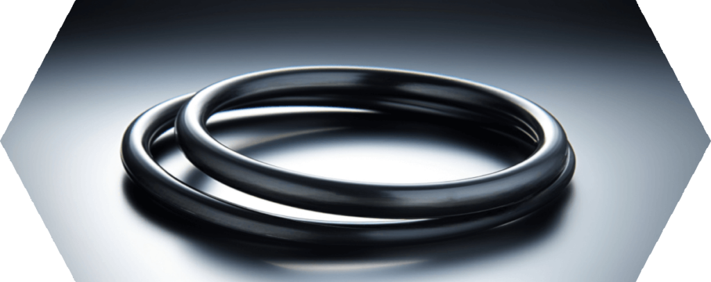
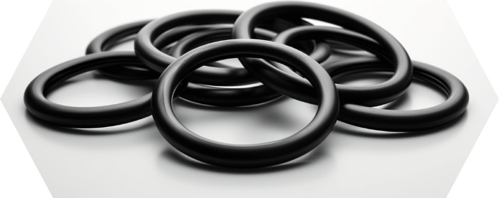
O-ring is a collective term for a circular sealing element with a round cross-section. Although an O-ring can also be shaped into an oval form, for example, due to its flexible properties, the standard case is a circular sealing point.
It is found, for example, at the joint between two pipes, but also in many other connections between two components.
Elastic material properties are part of the general definition of O-rings. These make it possible to deform O-rings and adapt them to the geometry of the sealing point.
These elastic properties are characteristic of rubber materials, so they are used as a material for conventional O-rings. However, elasticity does not only refer to the shape of the O-rings, but above all to the cross-section.
This is because O-rings must undergo a certain elastic deformation of the cross-section in the installed form in order to build up a sealing effect at all.
This has to do with the structure of a seal. The two components to be sealed each meet with one surface.
Between them is the O-ring, which ensures the tightness of the connection. The dimensions of the components are defined in such a way that the components exert a compressive force on the O-ring. This deforms the circular cross-section and creates the sealing effect.

#2 O-rings: Functional principle of the sealing effect
The reliability of the sealing effect is ultimately determined by the fact that the bond between the three central components of a seal is right.
This is because the inner sealing surface, O-ring and outer sealing surface must be positioned precisely enough in relation to each other. A uniform deformation force then acts on the O-ring.
As a result, the sealing element adapts to the surfaces of the components and thus closes any gaps. The degree of deformation is defined as a percentage change in the cross-section. This measure is also called compression.
Irregularities in the surfaces of the components result automatically from the mechanical processing.
During turning or milling, small irregularities occur in the workpiece surface that are permeable to liquids or gases. The deformation of the O-ring closes such surface defects and creates really tight connections.
Example of sealing effect
A common example of the use of O-rings as a sealing element are pistons and cylinders. These are mechanical components that are found in combustion engines as well as pneumatic and hydraulic systems.
The piston moves up and down in the cylinder as a medium exerts pressure on it. For this purpose, the cylinder bore must be sealed as one sealing surface against the circumferential surface of the piston as the second sealing surface.
Otherwise the piston cannot transmit any mechanical force. The media from the upper and lower areas of the cylinder would then also mix. In the case of pneumatic cylinders, these are lubricating oil to reduce friction and air as the medium for power transmission.
O-rings seal the gaps between the piston and cylinder, ensuring a clean separation between the two areas. This is particularly problematic in the case of excessive surface defects.
A well-known example is severe longitudinal scoring in the cylinder bore, which a sealing element can no longer compensate for. This leads to leakage. In a combustion engine, this is tantamount to serious engine damage, although other sealing elements are used here.
When installed, O-rings do not sit loosely between the two components, but in a defined position.
This installation space is also known as an O-ring groove. It runs in a circle through one of the components of the sealing system. During installation, the O-ring is either inserted into the groove from the front or snapped in while being slightly stretched or compressed.
This is necessary if the groove is only accessible from the side. Only the part of the seal that protrudes from the groove can be deformed.
The tight fit of the O-ring in its groove ensures secure installation and damage-free operation.
#3 O-rings: Differentiation from other sealing elements
The two key features of O-rings are their round profile cross-section and their elasticity. These properties also distinguish them from other common sealing elements.
- Flat gasket: A flat gasket does not have a round but a rectangular cross-section. However, it can be used just like an O-ring for a flange connection between two pipes. It is also pressed between the two sealing surfaces to create the sealing effect. The starting material for production is usually flat materials made from different materials, from which the seal is cut. Laser cutting is widely used. Flat gaskets do not have to have the elastic properties of an O-ring, so paper and fiber materials are also used in addition to rubber. In addition to round shapes, rectangular and irregularly shaped contours can also be produced.
- Profile seal: O-rings can also be defined as profile seals with a circular profile. In practice, however, profile gaskets are primarily understood to be gaskets with a different profile geometry. These are, for example, lip seals, U and D profile seals or other hollow chamber profile seals, which are typically used as continuous material. They can be found on doors and windows in the home, where they serve as sound and heat insulation. Of course, they are also used in industry. They share the elastic properties of O-rings, but are usually joined loosely instead of having a closed shape.
Defined profile, elastic behavior: O-rings can be clearly distinguished from other types of seals and this is also reflected in the specific manufacturing process.

#4 O-rings: Production and tolerances
O-rings have a circular cross-section and must also behave elastically. This gives rise to a number of requirements for the production processes.
On the one hand, O-rings can hardly be cut out of a flat material as a semi-finished product, as the round profile cross-section would be lost.
Secondly, there should ideally be no seam where the joints of a continuous material are connected. This would almost inevitably lead to altered mechanical properties in the joint area.
In practice, two main processes are used to manufacture O-rings. They are suitable for the production of standard O-rings in large quantities.
- Injection molding: Injection molding is a widely used process in plastics processing. In this process, a plastic mass is melted under heat and pressed into a closed mold under pressure. There the mass can cool and solidify. When the mold is opened again, the solidified parts can be removed.
- Compression molding: A shaping tool is also used in compression molding, but this is referred to as a die. The starting product is sections of round tube, which are produced by extrusion. Once these blanks have been inserted into the die, the tool closes. In turn, pressure and heat act so that the blanks take on the O-ring shape in the die.
Both processes are regularly used in O-ring production. However, the focus is slightly different.
While injection molding incurs higher tool costs, it also offers greater efficiency potential. Short cycles and a high level of automation make the process the first choice for the production of very large quantities.
With slightly less automation potential, but also a lower investment sum, compression molding is ideal for the production of smaller series. However, the following applies to both methods: The manufacturer must have tools with the correct dimensions to produce a specific O-ring size.
Manufacturers also frequently offer impact vulcanization as a manufacturing process for O-rings in special sizes. An endless round cord is used for this. It is cut to length and connected at the ends.
However, the mechanical strength of the O-ring suffers as a result of this process. The joint acts as a weak point because the fabric bond is generally less pronounced there.
Vulcanization
The manufacturing processes not only give O-rings the right shape. They also give the base material the necessary elastic properties.
In addition to shaping, another process takes place in parallel: vulcanization. It causes the properties of the raw material to cross-link. In its initial state, the raw material does not yet have any elastic properties. These only develop under the influence of heat during production.
From a chemical point of view, this turns rubbers into elastomers. This is a category of plastics that is characterized by its high elasticity. They are still referred to as rubbers in practice.
They are characterized by the fact that their individual molecules are strongly cross-linked.
This prevents them from shifting against each other permanently when the body is deformed. Instead, they swing back to their original state after being relieved of a deformation.
The tools determine the dimensions of the O-rings in their finished state. This in turn influences many subtasks in the design of an O-ring seal, so that size standards make work easier in practice.

#5 O-rings: Tables and dimensions
Two key dimensions define O-rings from a geometric point of view: the diameter of the ring and the diameter of the circular cross-section (cord thickness, CS for short). The inner diameter (ID) of the ring has established itself as the nominal dimension, so that the general size designation is based on the “ID x CS” scheme.
This specification determines the dimensions of the O-ring. However, material, tolerances and quality requirements should also be defined for an order. This is highly recommended, at least for more demanding applications.
Standardized size tables are available to simplify working with O-rings. They are part of the associated national and international O-ring standards. In addition to the definition of the sizes and their designation, these also regulate other areas of O-ring application.
Buyers of O-rings therefore do not have to list all the requirements themselves when ordering O-rings. You can also refer to the standard specifications of the appropriate standard. This gives you O-rings of a defined quality.
#6 O-rings: Overview of the most important standards
The standards and their associated O-ring tables have different histories. There are industry-specific standards as well as general standards.
National and international standards exist in parallel, whereby the users of O-rings are free to decide which standard to apply. The following tables are used most frequently.
AS568
AS568 is the dominant global standard for O-rings in imperial dimensions. Although “AS” stands for Aerospace Standard, O-rings in the standardized sizes are used in all industries today.
The size table numbers the defined combinations of inner diameter and cord thickness consecutively so that this number allows clear identification. While the cord thicknesses defined in inches range from the equivalent of 1.02 to 6.99 mm, the maximum inside diameter is approx. 660 mm.
The standard is also used in countries with a metric system. This applies to the procurement of spare parts as well as to the design of new systems.
BS 1806
BS 1806 is a British standard. The size chart also contains information on the inner diameter and cord thickness in inches.
Although the size table partially overlaps with AS568, it is still relevant because it defines O-rings in dimensions that lie between the size increments of AS568.
DIN 3771
DIN 3771 is a German standard for O-rings in general sealing applications. In accordance with the official measurement system, the size chart defines metric dimensions.
From a global perspective, it is therefore the metric equivalent of the AS568. The size tables of both standards together cover the vast majority of all common metric and imperial dimensions.
However, DIN 3771 covers much more than just the size table and the correct designation of the O-rings. It also defines the permissible tolerances and other quality-relevant properties of the sealing elements.
In addition, part of the standard describes the procedure for the correct design of the installation space. This provides technicians with comprehensive support in the design of seals.
ISO 3601
This international standard combines imperial and metric measurements in its size table. In this way, it combines and standardizes the requirements of the prevailing individual standards.
As a result, it has largely replaced not only the German DIN 3771 standard, but also many other national standards in practice. The standard also takes a very comprehensive approach to the other content.
Similar to DIN 3771, it specifies tolerances, installation spaces and quality. Together with the O-ring dimensions, these are decisive factors for a functioning seal.
When it comes to materials, however, ISO 3601 goes far beyond all other standards. It defines minimum requirements for common rubber materials and thus provides users with additional safety. Finally, O-rings designated as conforming to standards must meet these requirements.
ISO 3601 in practice
Finding a suitable O-ring for a given installation space: this is a standard task in the maintenance of technical systems. This is because the interaction between the O-ring and the installation space determines the compression and therefore the sealing performance.
Existing seals often offer room for improvement in this respect and a more suitable O-ring can be fitted in the existing system. Size charts such as those in ISO 3601 make this task easy.
Depending on the application, the ideal size can be found in the tables.
It works the same way the other way round. If the size of the O-ring is fixed, technicians can read off the specifications of the standard for the appropriate installation space. This means that new seals can be ideally designed right from the start.
However, some existing installation spaces can also be reworked to accommodate a more suitable O-ring. This makes it possible to subsequently increase the performance of a seal.

#7 O-rings: Advantages of size charts
The relevant O-ring standards contain more than just size tables and regulations on the designation of sealing elements.
They are an important guideline for the correct design of seals. However, these size charts are particularly valuable for another area: for purchasing O-rings.
Here, they can reduce complexity and simplify supply relationships. This can be attributed to three factors in particular.
- Quality: O-rings that are offered with reference to a standard must also meet the requirements of this standard. For many simple O-ring applications, it is therefore not necessary to specify your own tolerances or permissible surface deviations. If they are manufactured in standardized sizes, O-rings also come from mass production. Stable conditions and defined process controls prevail here, so that a high and consistent product quality can be expected.
- Price: Standard O-rings are in high demand from a wide range of industries. At the same time, the standards offer additional transparency, making it possible to compare prices between different providers. Thanks to the attractive price level, users can also choose higher-quality materials for standard sizes without multiplying the costs. This increases the durability of the seal and at the same time the overall efficiency.
- Availability: Whether an unplanned defect or periodic maintenance, the availability of O-rings can be critical for the operation of machines or entire systems. Without the right O-ring, construction machinery or entire food production lines would stop. The use of standardized O-rings is the best insurance against expensive delivery problems. Suppliers have O-rings in standard sizes made of many materials in stock. They can also usually supply special material qualities at short notice.
The use of standardized O-rings simplifies the entire process chain from the initial design to the maintenance of a seal.
In this way, users create a more reliable seal at lower costs and thus optimize the entire life cycle of the technical system concerned.

#8 O-rings: Requirements for materials
The different characteristics of O-ring materials allow the material with the best suitability to be selected. Technicians always have to find a compromise between fulfilling the different requirements. These can be grouped into several categories.
- Mechanical properties: O-rings are under pressure during use because they are pressed between the sealing surfaces. The hardness of an O-ring determines how much it deforms under a compressive force.
Less hard O-rings adapt better to the sealing surfaces. However, they can also be damaged more easily by other influences. Elasticity is measured by how much permanent deformation an O-ring retains once it has been pressed.
This material-dependent characteristic value is referred to as compression set.
The better O-rings spring back, the more adaptable they are in the long term when the position of the sealing surfaces in relation to each other changes. In addition to pressure, O-rings are also subjected to frictional loads in many applications.
After all, pistons and cylinders move against each other regularly. The O-ring rubs against at least one of the sealing surfaces. Materials with low friction withstand such operating conditions more easily and ensure smooth movement.
O-rings also have to be stretched frequently to get them into their mounting position. Materials with lower elongation at break must be handled with particular care by the personnel during installation.
- Media resistance: Air and oil are just two examples of media with which O-rings come into contact during the operation of technical systems. But O-rings don’t just seal pistons and cylinders.
They can also be found at the connection points of pipelines or at inspection flaps on production facilities in the chemical, pharmaceutical or food production industries. Therefore, almost all media can act on O-rings.
Acids, alkalis, oils and greases or solvents are common contact media. Not every O-ring material reacts in the same way when it comes into contact with a certain chemical. After all, solvents mainly attack substances that have a similar chemical structure.
The different O-ring materials have an individual composition that determines how they behave in contact with the media. If they are susceptible to a certain medium, this can cause them to swell or shrink excessively. The sealing effect suffers as a result. - Temperature resistance: The third component for material requirements is thermal stability, the term temperature resistance expressing the temperature range over which the properties of a particular material remain sufficiently stable.
Many O-rings gradually lose their elastic properties under heat. This is noticeable through a higher compression set.
The chemical processes between an O-ring and a contact medium can also run faster or slower depending on the temperature.
The requirements for mechanical properties, media resistance and temperature suitability of O-ring materials cannot be separated from each other. After all, they influence each other.
For example, a material may be well suited for permanent contact with hot water up to 80 degrees. However, if the medium becomes significantly hotter, the O-ring quickly loses its mechanical properties and loses its sealing effect.
If this is to be expected, the engineers must select a different material with better hot water suitability. At the same time, they must not lose sight of the basic mechanical properties.
#9 O-rings: The most important materials at a glance
Numerous different basic elastomers and even more different material mixtures: Today’s O-ring range offers many options for selecting the right material. In practice, certain areas of application have emerged for some materials.
FFKM O-rings
FFKM is a chemically highly resistant O-ring material. Virtually no chemical can attack this material.
This makes FFKM O-rings suitable for applications in all industries. The extremely high temperature resistance also contributes to this.
In a standard quality, the general upper temperature limit of FFKM is 260 degrees. Special recipes are even stable up to 340 degrees. FFKM is a so-called fluorinated elastomer. The material is also known as perfluoro rubber, whereby the fluorine content is responsible for the particularly good media resistance.
Due to the complex processing, FFKM is a very cost-intensive O-ring material. In practice, FFKM is also often referred to by common trade names. These include Kalrez from Dupont and Simriz from Freudenberg.
FKM O-rings
Like FFKM, FKM is also a fluorinated elastomer. However, the fluorine content of FKM is less pronounced. This results in slightly lower media resistance compared to FFKM.
The heat resistance also suffers from the reduced fluorine content, so that the maximum application temperature is 200 degrees.
Although FKM is clearly inferior to the high-performance material FFKM, the material still offers high overall media resistance over a wide temperature range.
The higher elasticity compared to FFKM is positive. For many applications, the performance profile of FKM is more than adequate and guarantees reliable seals. At the same time, users benefit from the significantly lower cost level.
This makes FKM a standard material in many industries. Manufacturers and users also refer to FKM as FPM or by the brand name Viton.
VMQ O-rings
O-rings made of VMQ material are also known as silicone O-rings. Silicone as a basic elastomer is characterized by a particularly high degree of purity.
This is why the material is transparent in its basic state. When used as an O-ring, this has the advantage that the material hardly interacts with other substances. This means that there is hardly any undesirable influence on substances that come into contact with the O-ring.
This makes the material suitable for use in particularly sensitive areas. For example, medical and food technology have very high requirements for the materials used in production processes.
Silicone is not only harmless to health, it is also odorless and tasteless, so it does not affect the taste of food. In addition, VMQ can be used in a very wide temperature range.
The material retains its sealing properties from very low temperatures down to -60 and up to 230 degrees. The material’s weaknesses are its high mechanical abrasion and low elasticity.
EPDM O-rings
EPDM is an interesting alternative to FKM for many applications. This is especially true if the O-rings come into contact with hot water and steam. The material is therefore widely used in the heating and sanitary sector.
However, it is also suitable for use in the food industry due to its harmlessness. Here too, the material benefits from its insensitivity to hot water and steam.
Many production facilities use steam sterilization for regular cleaning. Very hot steam is used here, which can damage other sealing materials. In terms of abrasion resistance, the material is at a very high level, making it suitable even if the sealing point is regularly moved.
In addition to the general name EPDM, the material is also sold under trade names such as Keltan, Vistalon or Nordel.
Features | Materials | ||||
FFKM | FKM | VMQ | EPDM | NBR | |
Abrasion resistance | good | good | sufficient | good | good |
Compression set | excellent | very good | good | good | very good |
Ozone resistance | excellent | very good | very good | good | inadequate |
Resistant to oil and grease | excellent | very good | sufficient | inadequate | good |
Resistance to hot water/ steam up to | 210°C | 120°C | 100° | 150°C | 80°/- |
Upper temperature limit in standard mixture | 270° | 200° | 200° | 150° | 100° |

NBR O-rings
In contrast to EPDM, the O-ring material NBR has its weaknesses with steam. However, it has very good mechanical properties to offer. Above all, this includes high tear and abrasion resistance.
Even if the sealing point is exposed to strong external influences or frequent movements, NBR is elastic enough to seal it reliably.
However, the use of NBR O-rings in the ambient air and outdoors should be avoided. The ozone contained in the air attacks the material and causes it to lose its sealing effect.
One remedy is to use special compounds that contain ozone protection agents. At 100 degrees, the heat resistance of the material is significantly lower than that of alternative O-ring materials. Large manufacturers market NBR O-rings under the brand names Perbunan or Europrene.
Material mixtures
Modern O-ring materials have many components whose mixing ratio is determined by formulations. These individual formulations are also known as compounds.
In addition to the basic elastomers, many other substances are incorporated into an O-ring. They are primarily used to specifically change the properties of the end product.
For some substances, however, the main focus is also on simplifying the processing procedures. The possibilities are many and varied, as formulation components can influence the color, aging resistance and elasticity of the O-rings, among other things.
While additives that are added in small quantities are referred to as additives, so-called fillers are used in higher concentrations. In addition to improving properties, they also serve to reduce costs. Finally, the content of the base elastomer decreases as its proportion increases.
Different compounds with a common base elastomer can differ considerably from one another. While an FFKM O-ring in standard quality is resistant up to 260 degrees, heat-optimized compounds can also withstand continuous temperatures of up to 330 degrees.
However, the media resistance of the O-ring materials in particular can hardly be summarized.
For example, a material may be sensitive to silicone oil, whereas it is not susceptible to animal oils.
Only detailed resistance lists can therefore tell whether an O-ring material is suitable for specific contact media. These represent the suitability of each material for several hundred specific substances.
#10 O-rings: flange seal, piston seal and rod seal
The design of the installation space begins with a general examination of the sealing point. Depending on the connection to be sealed, two applications of O-rings can be distinguished.
They can be used as stationary (static) or moving (dynamic) seals. This is the difference: Unmoved seals are found wherever the two components to be sealed against each other do not move regularly in relation to each other.
Components that are in a recurring relative movement form a dynamic seal.
While the static seal is the absolute standard case for the use of O-rings, dynamic seals are more critical.
There are many materials that are generally suitable for moving seals and friction can be minimized by designing the installation space appropriately. However, technicians should also consider alternative and more efficient types of sealing when designing the system.
In addition to the distinction between moving and non-moving seals, there is another important categorization. It refers to the type of installation of the sealing elements.
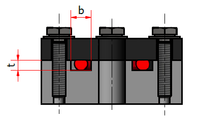

Flange gasket
The flange gasket is probably the simplest case for the installation of an O-ring. With this type of seal, the O-ring is located between the joints of two pipes, for example. Both are equipped with a flange for the screw connection.
In addition, there is a groove in one flange that accommodates the O-ring. This groove is arranged axially to the mounting direction.
The O-ring can be inserted into the groove from the front before the connection is closed and secured by tightening the screws. This deforms the O-ring by the defined amount so that the sealing effect is achieved.
The compressive force that leads to compression follows the longitudinal axis of the pipes in the same way as the installation direction. This type of seal is therefore also referred to as an axial sealing system.
Such flange gaskets are not only found on pipe connections, but also on the closure of maintenance flaps and other inspection openings in pipes and technical devices. A flange gasket is always a stationary gasket, so that mechanical friction caused by the movement of the components in relation to each other is irrelevant.
Piston seal
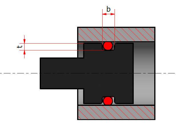
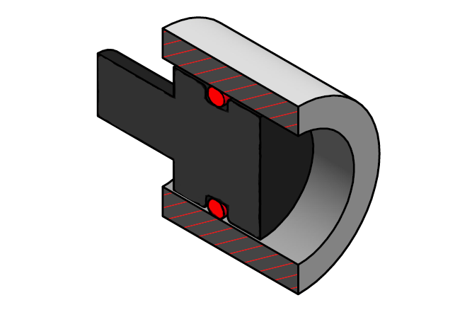
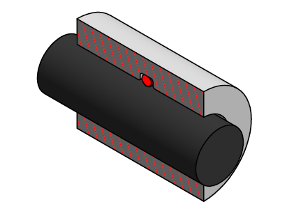
A piston seal differs from a flange seal primarily in terms of the installation direction of the O-ring and the positioning of the components in relation to each other. This is because the two components to be sealed are inserted into each other.
A piston is located in the cylinder, with the sealing surfaces lying against each other all around. In between is the O-ring, which fills the gap between the two components. This means that the O-ring cannot simply be inserted into the groove from the front as with the flange seal.
The groove of the piston seal is located on the outer diameter of the piston. Before assembling the components, a fitter must insert the O-ring and then guide the parts into each other. Pressing then takes place between the sealing surfaces of the piston and cylinder – orthogonal to the mounting direction of the two components.
Piston seals are therefore also called radial sealing systems.
This type of assembly allows the O-ring to seal in two ways in a piston seal. While it sits largely motionless in the groove in the piston and statically seals this side, it slides over the cylinder bore on the other side.
In most cases, a piston seal is therefore also a moving seal. Based on the sealing effect on the outer diameter, a piston seal is referred to as an external sealing design.
Rod seal
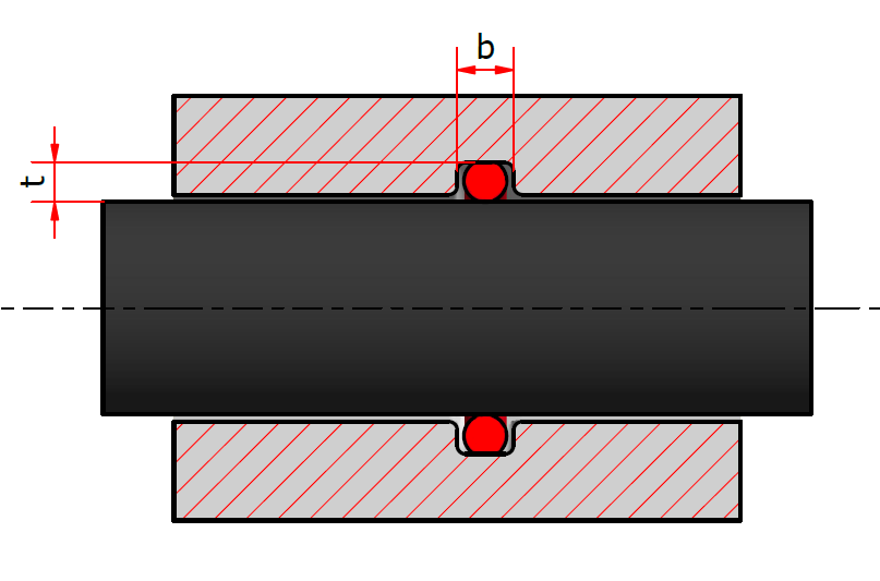
Rod seals are also used to seal pistons and cylinders. What has changed, however, is the position of the installation groove for the O-ring.
Instead of in the inner part as in the piston seal, the groove in the rod seal is in the outer part or cylinder. This means that the outer diameter is statically in contact with the base of the groove in the cylinder. However, when the piston moves in the cylinder, the inner diameter slides over the piston surface.
The O-ring therefore has an internal sealing effect. The direction of the compression does not differ from that of the piston seal, so that this is also a radial sealing system.
#11 O-rings: rectangular groove, trapezoidal groove and triangular groove
The installation type indicates the orientation in which the deformation acts on the O-ring. It also provides information on how the installation groove is arranged in the components. The groove can also be shaped in different ways. Here, too, there are advantages and disadvantages in production and installation.
Rectangular groove
The rectangular groove is the simplest and most economical form of O-ring installation space. Because the flanks of the groove are essentially at right angles to the base of the groove, the geometry can be produced very easily using standard machining processes.
When turning the groove, the tool can engage in the workpiece across the entire width. This is an economical way of creating a sufficiently precise installation space.
Trapezoidal groove
Trapezoidal grooves are also known as dovetail grooves. The term describes the arrangement of the groove flanks in relation to each other.
While the width of the groove is maximum at the base, the flanks move towards each other at the top.
This narrows the free space in the groove to the surface of the component. Due to its special shape, this groove is suitable for fixing O-rings in the groove. This means that they cannot move across the entire width as with the rectangular groove, but are fixed in place.
In practice, this is particularly useful if the seal is opened frequently. The groove holds the O-ring in position, thus reducing maintenance work and the risk of damage.
Compared to the rectangular groove, however, the manufacturing costs are much higher, so that the trapezoidal groove is only used in justified cases.
Triangular groove
Grooves in flange connections can also be produced as triangular grooves. When installed, the O-ring is not pressed between two sealing surfaces, but between three contact surfaces.
As a result, it is difficult to precisely maintain the target values for the deformation of the O-ring. The installation space also offers little room if the O-ring in the media contact increases its volume.
The triangular groove is also a challenge in terms of compliance with manufacturing tolerances. It is therefore only recommended in special cases. For example, it can help to identify special dimensional requirements for one of the components.
#12 O-rings: Relevant dimensions for the groove geometry
Cord diameter of the O-ring, sealing gap between the two components to be sealed and the depth of the installation groove: The combination of these parameters determines the sealing effect .
If the technician changes one of these values during the design, the compression will also change. Therefore, the sealing system must always be considered in its entirety.
When determining the dimensions of the groove, the main focus is therefore on the depth.
Groove depth
The groove depth is an essential dimension for determining the subsequent compression of the O-ring.
A minimum compression is necessary for a permanently stable sealing system. From this it can be deduced that the groove depth must always be less than the cord thickness of the O-ring. Under pressure, the material of the O-ring slides into the unevenness of the sealing surfaces and evens them out.
Pressing also compensates for inaccuracies in the positioning of the components in relation to each other. Finally, there may be a more or less pronounced eccentricity between the piston and cylinder.
If the nominal compression is too low, there may be no compression at all at a certain point in the diameter and therefore no sealing effect.
Excessive compression is also counterproductive, as the deformation forces on the O-ring increase.
Friction is also of particular importance for dynamic applications. The more the O-ring is deformed, the greater the resulting friction. This not only causes energy losses in the technical system, but also mechanical damage to the O-ring.
In general, the values for the recommended compression for static and dynamic sealing cases can be specified as follows:
- Static seal: 15 to 30 percent
- Dynamic seal: maximum 20 percent
The groove depth must be selected so that, in conjunction with the other components, it ensures compression within the respective target range.
Stick-slip effect
A phenomenon known as the stick-slip effect can often be observed in dynamic seals.
This process, also known as jerk sliding, results in a change in the friction conditions at the sealing point while the machine parts are moving.
As a result, the desired movement is not uniform, but jerky and jerky. This also generates noise and vibrations that can disrupt the respective process.
From a physical point of view, jerking occurs at the transition between static and dynamic friction. The lower the static friction, the more uniformly slow movements can be carried out.
To avoid jerking, O-rings with optimized friction values are preferred in dynamic seals. The grouting and thus the appropriate groove depth can also minimize friction.
Groove width
Together with the depth, the width essentially determines the shape of a rectangular groove.
The groove width has no direct function in connection with grouting. It is more decisive for how far the O-ring can move to the sides when installed.
To accommodate an O-ring, the groove width must be at least equal to the cord thickness of the O-ring. In practice, however, larger groove widths are selected. This necessity results from the swelling behavior of the O-ring materials.
When they come into contact with certain media, they absorb components of it and increase their volume.
This means that the O-rings require more space in the groove. A wider groove provides space for the O-ring to spread out to the sides. It is therefore standard to design the width so that the pressed O-ring takes up 85 percent of the groove.
The groove width also has another function in pressurized seals. This ensures that medium can enter the sealing gap evenly from the pressure side across the diameter.
This creates a homogeneous compressive force on the O-ring, which benefits durability. A groove that is too wide is counterproductive, especially for seals with changing pressure conditions.
The O-ring can move from one side of the groove to the other if the direction of the pressure changes. This in turn generates friction, which mechanically damages the O-ring.
Further design parameters
While the depth and width of the groove essentially determine this, technicians have to specify even more in detail to ensure that the installation space is designed correctly. This includes the groove radius, angle of the groove flanks and insertion chamfers.
Groove radius
All edges with which the O-ring comes into contact in the installation position must be rounded.
This requirement can even be extended to all edges that the O-ring must pass over during assembly. After all, all sharp edges represent a potential source of damage.
The O-ring can be crushed or material can be sheared off, which significantly reduces the service life of the seal. With regard to the installation groove, the focus is particularly on the top and bottom edges of the groove.
The edges between the groove base and groove flanks on the one hand and the groove flanks and surface on the other must be provided with a radius.
Angle of the groove flanks
Although the flanks of a rectangular groove are generally at a right angle to the groove base, variations are possible. However, it is recommended to increase the angle by a maximum of 5 degrees.
This is primarily used to meet manufacturing requirements.

#13 O-rings: The most important approvals
In addition to the choice of installation type and the correct dimensioning of O-rings and installation space, another topic is relevant for many areas of application: industry and application-specific approvals.
The food industry, for example, places high demands on production equipment. For reasons of quality assurance and health protection, the O-rings used must not affect the properties of the food.
By obtaining the corresponding approvals for their O-rings, suppliers prove that their products meet the relevant requirements. In practice, the following approvals are particularly relevant.
Food approvals
FDA (Food and Drug Administration) approval is an American set of regulations, but it is used worldwide.
Finally, only goods that are manufactured under FDA-compliant conditions may be placed on the market in the user countries. In the food sector, operation is characterized by high temperatures and aggressive cleaning procedures.
FDA-compliant O-rings meet the material requirements to prevent undesirable interactions with the products under these conditions. This means that toxic contamination or influences on odor and taste are largely excluded with FDA O-rings.
Important food approvals include FDA and 3-A Sanitary Standards. In addition to the food sector, the approval also focuses on applications in pharmaceutical production.
In practice, it is used, among other things, to prevent the extraction of sealing materials in contact with fatty dairy products.
If the material is not selected correctly, the greases can release substances from the O-rings, which then enter the products. O-rings with an approval according to 3-A Sanitary Standards are specifically tested for their extraction behavior.
Approvals for the pharmaceutical sector
Even higher standards are applied in the production of pharmaceuticals and medical products than in the food sector.
The US Pharmacopoeia USP divides materials into 6 classes of biocompatibility. The decisive factor for the classification of an O-ring material is the extent to which it influences a living organism.
Regardless of whether sealing materials come into contact with medication or enter the human body as a component of an implant: It must be ensured that no rejection reactions occur.
Depending on the type of medical application, O-rings classified in one of the 6 USP classes must be selected.
Freedom from BSE/TSE-carrying ingredients is a common addition to FDA approval. Corresponding O-rings bear a seal that identifies them as “ADI-free”. This explicitly serves to exclude the possibility that the sealing materials contain components of animal origin (Animal Derived Ingredients, ADI).
If they are free of ADI, they cannot transmit animal diseases that are dangerous to humans, such as BSE.
Drinking water approvals
Drinking water distributed via the public network is a particularly protected commodity in many countries.
The high importance of drinking water for the health of residents justifies its special status. Many countries therefore maintain their own requirements for technical devices in drinking water pipes.
In Germany, the Elastomer Guideline (KTW) specifies the relevant requirements for sealing materials. O-rings for use in drinking water systems must pass a defined test procedure. O-rings are tested for
- Change in odor and taste
- Optical influence
- Extraction
If successful, they are included on a positive list of safe materials. The DVGW W270 approval adds a further perspective.
The German Technical and Scientific Association for Gas and Water focuses on the growth of microorganisms. Sealing materials for drinking water systems must keep the proliferation of such organisms to a minimum.
The German approvals are an example of national drinking water approvals. International equivalents are, for example, the British WRAS, the American NSF61 or the Austrian Ö-Norm. Many O-ring suppliers also refer to them when specifying their products.
Gas approvals
Gas is a hazardous substance that is used in households and industry alike. Due to the safety risks, strict requirements apply to the tightness of gas supply facilities.
In order to permanently prevent the escape of flammable gas, the sealing elements must have a high resistance to ageing.
Deformation under pressure is also an important criterion. In Germany, conformity testing of materials is carried out on the basis of DIN EN 549 or DIN EN 682.
The NORSOK M-710 standard sets a more specific application focus. This comes from an association representing the interests of the Norwegian oil and gas industry.
It was developed in response to the particularly demanding operating conditions in this area. O-rings in these applications have to withstand extreme pressure peaks and a wide temperature amplitude.
O-rings with NORSOK approval are therefore also interesting for many other areas of application with a similar load profile.
The high performance of the materials can also reduce the causes of pressure-related damage and thus enable more stable operation of machines and systems.

#14 O-rings: avoid causes of damage
Different materials, different installation types and application-specific approvals make it clear: the design of a sealing system is an extensive process with many influencing variables and dependencies.
At the same time, the sealing requirements are immense. After all, if it fails, there are usually consequences. It is therefore particularly important to know which factors stress O-rings during operation and how they can be controlled.
With this knowledge, many common causes of failure can be avoided from the outset. If the damage has already occurred, a targeted analysis will help to improve the seal.
The causes of damage to the O-ring cannot always be clearly separated. It is often a combination of several factors that weakens an O-ring to such an extent that it fails and loses its sealing effect. Nevertheless, four categories of causes of damage can be distinguished.
- Media influence
- Temperature and ageing
- Physical stress
- Manufacturing defects
The underlying active principles and countermeasures can be defined for each cause of damage.
#14.1 Exposure to media
The pairing of material and contact media is a decisive factor for the service life of an O-ring.
Engineers have to make the right choice from the large number of elastomer materials available to avoid undesirable interactions between the materials.
There are two main mechanisms at work here: swelling and extraction. During swelling, components of the contact medium enter the O-ring. This leads to an increase in the volume of the sealing element.
As a result, the compression of the O-ring between the sealing surfaces increases. This increases friction, which is a particular problem in dynamic applications. However, another consequence is relevant for all applications.
If the groove width does not provide enough space for the O-ring to deform further towards the flanks, the O-ring can be pressed out of the groove, causing considerable mechanical damage.
During extraction, the damage mechanism rotates and the contact medium releases components from the sealing material.
Accordingly, the O-ring loses volume, which reduces the compression. This can easily lead to a shortfall in the minimum compression and leaks occur.
As a rule, this is not done simultaneously around the entire circumference of the O-ring, but first where the lowest initial compression is present due to the tolerance positions of the components.
O-rings with a high plasticizer content are particularly affected by volume shrinkage. Careful recipe selection can therefore limit this problem. Extraction and swelling have an effect on the volume of the sealing element and thus on the compression. The two damage mechanisms can be recognized by these characteristics:
- Strong increase or decrease in volume
- Mechanical damage as a result of pressure and friction
Aggressive media can also directly attack the material cohesion of the O-rings. This jeopardizes the elasticity, the central sealing-relevant property of the O-ring material.
This is due to the highly pronounced network structures between the molecules. These chains ensure that the material always springs back to its original position after a temporary deformation.
It is precisely these structures that can suffer from contact with harmful media. The long-chain bonds are then divided into shorter sections, which reduces the overall elasticity.
Post-crosslinking can also occur, whereby new bonds are formed locally. This is also at the expense of elasticity.
The O-ring material becomes increasingly rigid so that it can no longer adapt to a change in the sealing point. If, for example, the position of the components in relation to each other changes due to an external impact, a damaged O-ring cannot securely close the gap.
After dismantling a failed O-ring, personnel should look out for the following signs in order to be able to determine the chemical attack:
- Softening of the material
- Sticky surface
- Brittle and cracked surface
It should be noted that the material changes described above mainly occur where the O-ring comes into direct contact with the harmful medium.
This helps to differentiate the chemical attack from other causes of damage that cause similar material changes.
Damage caused by assembly oil and grease
O-rings that are used in a piston or rod seal must be deformed for assembly.
This is particularly relevant for a piston seal. This is because in order to reach the installation groove, the fitter has to stretch the O-ring, sometimes passing over areas with a larger diameter or holes in the component.
Lubricants are used to facilitate this process in accordance with the general recommendation.
Assembly greases or oils reduce friction and thus protect the O-ring from mechanical damage. However, if care is not taken, the additives can cause chemical damage. For example, EPDM O-rings must not come into contact with mineral oil-based substances.
An alternative is silicone oil. However, this in turn can chemically attack VMQ O-rings. Care is therefore also required during installation to prevent chemical damage to the sealing elements.
#14.2 Temperature and ageing
Temperature-related damage to the O-ring is primarily due to the interaction between the material and the ambient air.
A higher temperature also increases the reaction rate of many chemical processes, which reduces the service life of the material. Two mechanisms, post-crosslinking and chain scission, have a harmful effect.
While additional bonds are formed in the material during post-crosslinking, making the material harder and less flexible, chain scission leads to the same result: the O-ring loses flexibility.
From the correlation between temperature and damage, it can be deduced that a higher temperature leads to a shorter service life of the O-ring.
If longer service lives are to be achieved, the technicians must either limit the temperatures in the process or use an O-ring material with better high-temperature behavior.
Compression set
The compression set is a metrologically determined value that provides information about the temperature behavior of an O-ring material.
O-rings are exposed to certain high temperatures in a deformed state over a defined period of time.
After the O-ring is relieved and gradually returns to the ambient temperature, it at least partially returns to its original shape. The permanent component of the deformation is referred to as the compression set.
The lower the compression set, the higher the resistance of the material to permanent deformation.
Even after prolonged deformation under temperature stress, it can return to its original shape to a high degree and thus seal the sealing point even under changing conditions.
O-rings retain a permanent deformation even if no elevated temperatures are applied. However, heat intensifies the effect. The method is therefore not only used to assess temperature behavior. General conclusions can also be drawn about the material properties.
The overheating of an O-ring as a result of its maximum temperature being exceeded is indicated by these characteristics:
- Superficial cracking
- Shiny spots
- Embrittlement
- Permanent deformation
In addition to choosing a particularly heat-resistant O-ring material, technicians have another design option to make a seal more robust. Safety reserves can be created by selecting an O-ring with a larger cord thickness.
Incidentally, O-rings also lose some of their elastic properties at low temperatures. Unlike heat, however, cold does not result in a permanent change in properties. After reheating, the O-rings regain their full elasticity.
In addition to the effects of heat, the ageing mechanism also falls into this damage category. Here it is not directly the ambient air, but above all the light that influences the O-ring properties.
UV light increases the concentration of ozone in the air. This ozone attacks the O-rings and leads to deep cracks in the material.
This leads to considerable damage to materials with a high susceptibility to ageing, especially in the warm months and outdoors. If stored incorrectly, certain O-rings can even be damaged by ozone before they are even put into operation.
However, not all O-ring materials are susceptible to attack by ozone. This phenomenon is particularly evident in NBR O-rings, which are often used in pneumatics and hydraulics.
EPDM or FKM, on the other hand, are unproblematic in this respect. There is also a remedy for NBR if the technicians use special ozone-protected material formulations.
It is also important to store them in a stress-free state and to shield them against excessive air exchange.
#14.3 Physical stress
Pressure, friction and their effects on the O-ring are among the most common causes of failure in practice.
Even carefully designed seals can fail due to this damage mechanism. O-rings can suffer mechanical damage during installation.
The assembly process illustrates the risks involved. While flange seals are generally unproblematic due to the good accessibility of the groove, there is an increased risk with piston and rod seals.
When fitting a piston seal, the O-ring must be stretched. This allows the areas on the component with a larger diameter to be traversed. Once it reaches the groove, the O-ring snaps into place and is firmly seated.
The other way round with the rod seal: the O-ring can only be pushed through the cylinder bore and into the installation groove with the help of compression.
In both cases, friction occurs because the inner or outer diameter of the O-ring slides over the component surface.
In the worst case, this can already lead to material loss on the O-ring as small particles detach from its surface. More critical, however, is the danger posed by sharp edges against which the O-ring is pressed.
Sharp-edged groove recesses, holes with missing deburring or unrounded edges can press into the surface of the seal and cause damage.
The spectrum ranges from small cuts to pinch-offs. Even if the initial damage is minor, it significantly reduces the service life of the seal.
After all, these pre-damages represent predetermined breaking points. Under operational stress, the damage quickly increases as they are exposed to media, temperature and friction.
The first physical damage can therefore already occur during installation. However, these mechanisms also continue to affect the sealing elements during the operating phase. Technicians must take these circumstances into account during the design phase.
They can then, for example, limit the effect of pressure on the O-ring. If strong pressure is exerted on the O-ring from one side, it is subject to a second deformation in addition to the compression. The force presses the O-ring against the groove flank facing away from the pressure.
The stronger the pressure and the softer the O-ring, the more easily the sealing element is pressed into the sealing gap between the two components. The material slides over the groove edge. If it is not sufficiently rounded, material is sheared off the O-ring.
As a result, volume is lost so that the defined compression decreases. This phenomenon is also known as fissure migration or fissure extrusion.
Gap extrusion
The term gap extrusion comes from the fact that in extreme cases large peelings form on the O-ring.
The further the O-ring is pressed into the sealing gap, the more material is separated by sharp edges. This can detach completely from the O-ring or remain on it as an extrusion vane.
Gap extrusion can be avoided if the designers minimize the size of the sealing gap.
However, there are technical and economic limits to this. After all, a precise fit places high demands on tolerances. If the operating pressure at the sealing point cannot be reduced any further, there is another option in the choice of material for the O-ring.
Tighter O-rings are less easily pressed into the sealing gap. If required, they can also be protected from contact with the groove edge by an additional support ring made of extrusion-resistant material.
Other key points of error in the design relate to grouting. Excessive compression favors permanent deformation of the O-ring and leads to excessive friction in dynamic applications.
Explosive decompression
Explosive decompression is another physical damage mechanism. Here, too, media pressure has a causal effect.
However, the mode of action differs significantly from gap extrusion. Elastomeric sealing materials have a more or less pronounced gas permeability. While lower gas permeability is more important for some applications than others, it always plays a role when high pressure is involved.
This is because gas penetrates the seal under pressure. This can escape with a gradual drop in pressure so that there are no further effects. However, if the pressure suddenly drops, the gas in the O-ring expands.
As a result, the gas tries to escape from the O-ring so that it can expand freely. However, the gas permeability is not sufficient for this. Because the gas escapes in an uncontrolled manner, the O-ring material is damaged.
Blisters and cracks form at the exit points. These in turn represent a point of attack for further stresses. O-rings damaged in this way can lose their sealing performance immediately or gradually.
Technicians can take precautions against explosive decompression by avoiding pressure surges in the system and allowing longer periods for the pressure to drop.
In terms of material selection, O-rings with high hardness and low gas permeability should be preferred. O-rings approved to NORSOK Standard M-710 are particularly suitable for these operating conditions.
With changing pressure directions, static seals are also subject to friction that should not be neglected.
Depending on the width of the groove, the O-ring moves to the side facing away from the pressure. The outer diameter of a piston seal slides over the cylinder surface, while the inner diameter is in contact with the groove base.
This friction can be controlled by reducing the groove width. Even a lower surface roughness
#14.4 Manufacturing defects
Manufacturing faults are a cause of failure that cannot be ruled out by careful design or professional installation.
The O-rings do not meet the necessary material properties for a reliable seal when they are installed. In use, their sealing effect then quickly deteriorates because the operational causes of damage attack the already weakened O-ring.
This applies in particular to insufficient cross-linking (under-vulcanization). The vulcanization process step gives the sealing material its elastic properties by forming a network structure between the molecules.
Temperature and time are the key parameters here. Deviations here or in the formulation lead to an insufficient degree of vulcanization and consequently insufficient elasticity. This is noticeable through a high compression set.
Such O-rings exhibit a high degree of permanent deformation and can only adapt slightly to changing conditions at the sealing point. A slight change in the positioning of the components in relation to each other is then sufficient for a leak to occur.
Other production-related problems lie in the area of cracking. This can be caused by contaminated tools or insufficiently mixed compounds.
Because a homogeneous mixture cannot form, damaged areas are created which become a point of attack during subsequent operation. Cracks can also form during demolding or reworking.
The best way to rule out production-related errors is to carry out detailed checks on incoming goods. Cooperation with reliable suppliers is also an important key.
Manufacturers and distributors of high-quality O-rings ensure stable quality through process-integrated controls.
Quality control of O-rings
Manufacturing errors or mix-ups during order picking: If the O-ring actually supplied deviates from the technical specifications, this can significantly reduce its durability.
Users of O-rings, on the other hand, are best safeguarded by carrying out a few basic checks themselves. This enables them to ensure as far as possible that the delivered goods meet the requirements.
Intensive cooperation with a reliable supplier can reduce this internal effort. Nevertheless, it is advisable to carry out these checks routinely:
- Density test: Density is a characteristic material parameter so that different materials can be distinguished from one another if the dimensions of the O-ring are known. In this way, material mix-ups can be ruled out. However, it is not possible to differentiate between individual recipes.
- Hardness test: O-ring materials are available in various hardnesses. The hardness is usually between 60 and 90 Shore A. The hardness can be determined approximately with a hardness measurement. In practice, however, many factors distort the result, so the procedure should be supplemented with further checks.
- Dimensional check: Incorrect dimensions can be detected by simple means using a measuring cone. More extensive equipment such as a measuring machine is required to check compliance with the tolerances.
- Compression set: The compression set is the measure of the elastic behavior of an O-ring. The test is therefore suitable for detecting recipe variations or processing errors. As the test relates to the central seal-relevant property and can be carried out with simple means, it is of particular practical relevance.
#15 O-rings: Secure assembly
Appropriate attention should therefore be paid to the assembly process. This prevents a high percentage of installation-related damage. In practice, the following damage patterns can be observed:
- Twisting: If there is too much friction when fitting an O-ring, it will not slide over the component surface, but parts of it will twist. The material is locally overstretched, so that the material structure is affected. This is shown on the surface by cracks that weaken the O-ring. Assembly oils and greases reduce friction.
- Overstretching: In the case of the piston seal, a certain amount of stretching is necessary for installation. Otherwise the O-ring cannot be moved over the diameter of the piston to the installation groove. Depending on the tensile strength of the respective material, certain elongations are permissible. If the harmless elongation is exceeded, the O-ring will be permanently damaged, just like when it is twisted. A mounting cone is suitable as an aid. It limits the expansion and ensures that the O-ring is loaded evenly over the entire circumference.
- Crushing: Crushing mainly occurs when pistons and cylinders are pushed into each other. Incorrect positioning means that the components do not slide into each other, but that the O-ring is pressed against a hard edge. Depending on the sharpness of the edges, this can result in crushing or shearing. As a countermeasure, insertion chamfers must be provided on the design side of the components. They ensure correct concentric positioning.
There are no significant differences between the various groove shapes in terms of the assembly process. The flange seal is the least critical of the installation types.
The installation space is fully accessible here. For piston and rod seals, on the other hand, the O-ring diameter must be expanded or compressed.
An expanding sleeve has become established as an aid for the piston seal and assembly pliers for the rod seal.
In general, the most important installation instructions can be summarized in these points:
- Use suitable assembly grease or oil to reduce friction
- Ensure that the installation space is clean and burr-free so that the O-ring is not mechanically damaged and the technical system is not contaminated
- Support secure installation by specifying sufficient insertion bevels and a high surface quality
- Do not twist or overstretch the O-ring, as this can cause permanent damage
- Observe the material properties to ensure the pairing of O-ring material and assembly grease and not to exceed the individually permissible elongation
A careful approach and the right tools make all the difference during installation. Together with an installation-oriented design, this can prevent many premature leaks.

#16 O-rings: Standardized bearing
In addition to assembly, the storage of O-rings is a factor that often receives too little attention.
Because here too, there are risks that can be effectively avoided through good organization. In addition, the right approach to storage also increases cost-effectiveness.
Storage-related damage
Vulcanization gives elastomers their seal-relevant properties: they are flexible and can therefore adapt to the sealing surfaces.
At the same time, they retain their original shape, which is also decisive for the sealing effect. This means that from now on, the O-rings must be specially protected from harmful influences at all stages of storage by the manufacturer, dealer and user.
General requirements for storage can be formulated. They ensure that the shape and elasticity of the O-rings remain stable.
- Avoid pressure load: If a heavy object rests on an O-ring or if it is stretched, it can become permanently deformed.
- Limit draughts and sunlight: Strong air exchange and sunlight age some elastomers, so a dark, enclosed room should be used for storage.
- Reduce temperature peaks: Strong heat development or cooling reduce the flexibility of the material. O-rings stored at low temperatures should be warmed to room temperature before installation. Hot storage can permanently impair flexibility.
The maximum storage life of elastomers should also be taken into account. Even under perfect conditions, the components are subject to changes in properties.
Elastomer | Maximum storage time |
NBR | 6 years |
EPDM | 7 years |
FKM & VMQ | 10 years |
FFKM (ECOLAST) | 13 years |
Optimum storage concept
The storage conditions of the O-rings are a frequent source of damage, especially for the user. However, many risks can be eliminated by creating a defined storage concept.
The best way to do this is to have only one storage room for gaskets per operating site. This is the best place to ensure the desired conditions in terms of climate and sunlight.
Damage caused by heavy components or similar can also be prevented by a suitable storage system.
Single-variety storage also limits the risk of confusion when picking O-rings.
O-rings should ideally be stored in the packaging in which they are delivered. Larger quantities can remain in cardboard boxes. The O-rings are usually contained in airtight PE film bags.
They should only be removed from this protective cover when assembly is imminent. The O-rings should therefore also be stored in the sealed bags.
A well-organized warehouse keeps a sufficient quantity of O-rings in stock under defined conditions. At the same time, the aim should be to keep stock levels to the necessary minimum.
Because, assuming a stable supply relationship, the demand-oriented purchase of seals saves costs. Users not only benefit from a smaller storage area, but also eliminate storage-related problems. Incorrect deliveries are also detected more quickly if there is no need for separate interim storage.
#17 Conclusion
The successful use of O-rings is the sum of numerous factors. Some of them influence each other, so that the chain of design, production, assembly and maintenance can quickly become complex.
The core task of a planner is therefore to select the right O-ring material for the pressure, temperature and media at the sealing point.
At the same time, the dimensions of the O-ring and installation space must ensure the necessary compression – even if friction, swelling and shrinkage occur. When installing the O-ring, it must again be ensured that the maximum permissible elongation of the selected material is not exceeded.
Despite the complexity, users can create economical and permanently reliable O-ring seals if they invest sufficiently in planning.
A coherent overall concept for sealing ensures a long service life and low production and purchasing costs.
“I am convinced that we should share our knowledge with the world. I hope I have been able to answer all your questions. If you have any further questions, please feel free to contact us at any time. We will be happy to help you.”

Lord of the O-rings
Author of the Sealing Academy
