
O-ring applications: fields of use at a glance
O-rings seal in a wide variety of designs. Which type of seal you choose depends on the direction of compression and the position of the groove. We explain flange, piston and rod seals along with material selection, groove design and installation.


- The most important distinction is the direction of compression: axial in the installation direction or radial at right angles to it.
- The flange seal is purely static and axially compressed. It is suitable for pipe connections and inspection openings.
- The piston seal is radially compressed, sealing outward, with the groove in the inner part. It is more economical and can be used both statically and dynamically.
- The rod seal is radially compressed, sealing inward, with the groove in the outer part. It is found above all in hydraulics and pneumatics.
- Material selection, groove geometry and installation method always depend on the pressure, medium, temperature and movement of the seal.
The main O-ring applications
O-rings are extremely versatile sealing elements. Thanks to their round shape and elastic properties, they can seal technical components against one another in a variety of configurations. They are equally suited to separating the interior of a machine or system from the environment.
Whether pressure, specific media or temperatures: correctly used O-rings reliably maintain the conditions inside the sealing system. To live up to this task, engineers must take the specific requirements of the respective application into account when designing a seal.
The most important distinction between different O-ring applications concerns the direction of compression. Viewed from the installation direction, the cross-section of O-rings can be compressed axially or radially.
Compression refers to the elastic deformation of the O-ring between the two sealing faces. It is necessary in order to close off the sealing faces cleanly. Through compression, the sealing element adapts to unevenness in the workpiece surfaces. Even components positioned slightly eccentrically to one another are reliably sealed by this preload of the O-ring.
This also matters because the positioning of the components can change at any time due to external influences such as an impact. Axial and radial compression are the two categories of common O-ring applications. They can be subdivided further and have specific requirements in terms of design, material selection and many other parameters.
Sealing type: flange seal
The flange seal is an O-ring application in which the sealing element is used purely statically. Here the sealing faces between which the O-ring is compressed are at rest. It is therefore a rigid connection, although this is usually made detachable with bolts. Flange seals are characterised by compression in the axial direction.
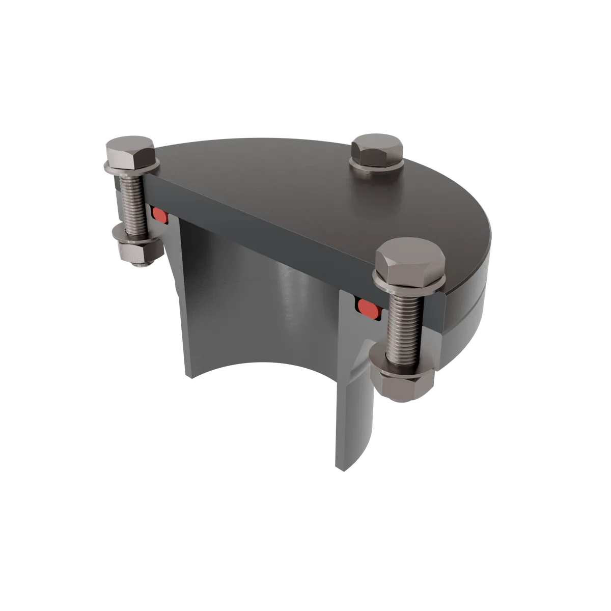
The deforming force therefore acts in the installation direction of the O-ring. Examples include connections between pipelines or inspection openings. Reducers for the line cross-section are also secured by means of a flange seal.
1. Materials
In principle, many elastomer materials are suitable for use as a flange seal. Because installation requires hardly any stretching, materials with low elasticity can also be used without problems. In the chemical and food industries, for example, the rigid but extremely media-resistant PTFE is a very common material for flange seals. EPDM is often used in plumbing and heating installations.
2. Groove design
When designing the groove for flange seals, it is above all important to note that the pressure direction dictates the installation position of the O-ring. Under internal pressure, the sealing element should rest against the outer groove edge; under external pressure, the other way round accordingly. In this way, the pressure increases the sealing effect.
3. Installation
Installation of flange seals is usually straightforward thanks to the easily accessible grooves. The O-ring can be inserted into the groove from the front without being deformed excessively. Under external pressure, only a slight stretching of the inner diameter is required; under internal pressure, a minimal compression of the outer diameter.
4. Fields of application
The flange seal with O-rings is found wherever round components are to be connected statically to one another. Flanges and the corresponding seals secure joined pipes, close off end points with covers and incorporate inspection openings.
Sealing type: piston seal
With the piston seal, the O-ring is compressed radially. The deformation therefore acts orthogonally to the installation direction. A further criterion characterises the piston seal: here the installation groove is located in the inner part of the seal, i.e. the piston. Compression takes place at the sealing face of the outer part.
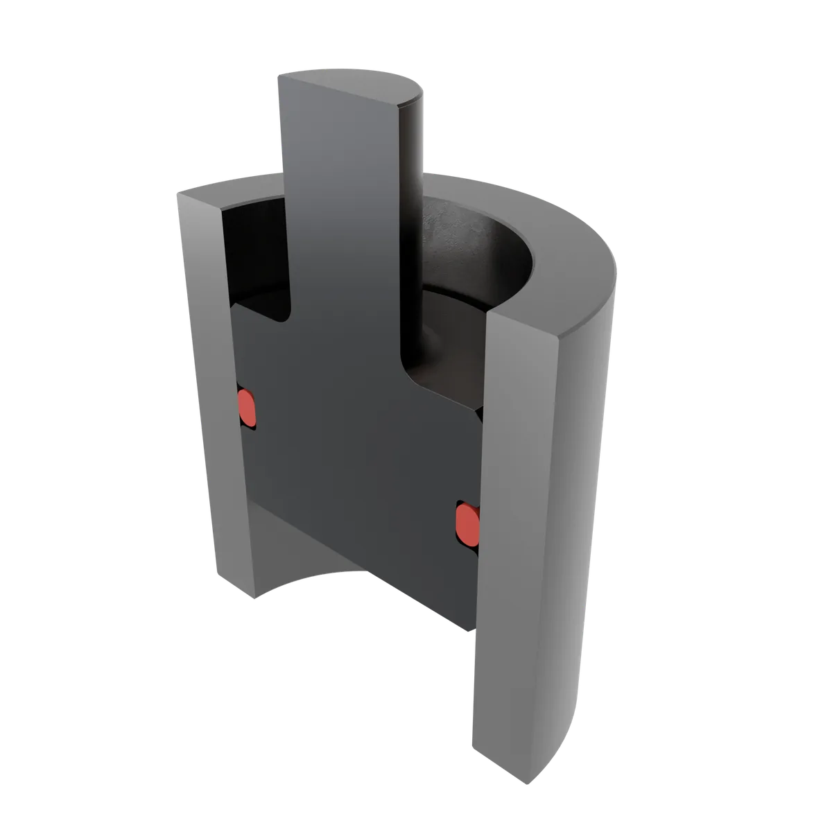
Piston seals are therefore also described as outward-sealing. They are generally more economical than rod seals, because the installation groove in the inner part is easier to produce with machining processes.
1. Materials
The piston seal can be used both statically and dynamically. Whereas in dynamic applications the load on the O-ring due to friction is particularly relevant, it is rather uncritical in the static sealing case. With one exception: in static seals, changing pressure conditions can cause strong friction. The O-ring then migrates alternately from one groove flank to the other, so as to be on the side facing away from the pressure in each case.
With dynamic seals, by contrast, the sealing faces regularly move against one another and thus also against the O-ring. The most common examples of this are hydraulic and pneumatic applications. Dynamic use as a piston seal calls for particularly friction-resistant materials. The abrasion-resistant materials include NBR, PTFE, EPDM and FKM.
2. Groove design
The groove design should also take dynamic use into account. A significantly reduced compression should be provided so that friction is limited to the technically necessary minimum. This protects the O-ring from premature wear and increases durability. Higher surface finishes of the sealing faces also contribute to durability.
In general, when designing the groove it is crucial to set the target value for compression via the depth of the groove. The width of the groove is determined depending on the expected swelling behaviour and the pressure conditions. The groove must be wide enough to allow for the increase in volume of O-rings in contact with certain media.
On the other hand, it should not be excessively large, as the O-ring can migrate under changing pressure conditions. The inner diameter of the O-ring is chosen to be somewhat smaller than the groove base diameter. In general, a stretching of the O-ring of 1 to 6 percent is recommended.
In addition to the actual groove, lead-in chamfers must be provided in the outer part of the piston seal. They help to position the piston and cylinder correctly and gently relative to one another during installation. Without the lead-in chamfers, there is a risk that the O-ring will be crushed by a hard workpiece edge.
3. Installation
When installing a piston seal, the O-ring must be stretched. Depending on the elasticity of the material, it should be assessed whether critical stretching can occur during installation. Careful warming and the use of installation aids can make fitting more convenient and safer. Installation cones ensure uniform stretching and make it easier to pass over edges.
4. Fields of application
This O-ring application predominates above all where two round components are inserted into one another. First and foremost, the piston and cylinder should be mentioned. These can be static or dynamic sealing cases.
Sealing type: rod seal
Rod seals share the direction of compression with the piston seal. However, with the rod seal the installation space of the O-ring is located in the outer part or cylinder. During design, the O-ring is selected so that it snaps into the installation groove slightly compressed. Compression is then created at the sealing face of the inner part or piston.
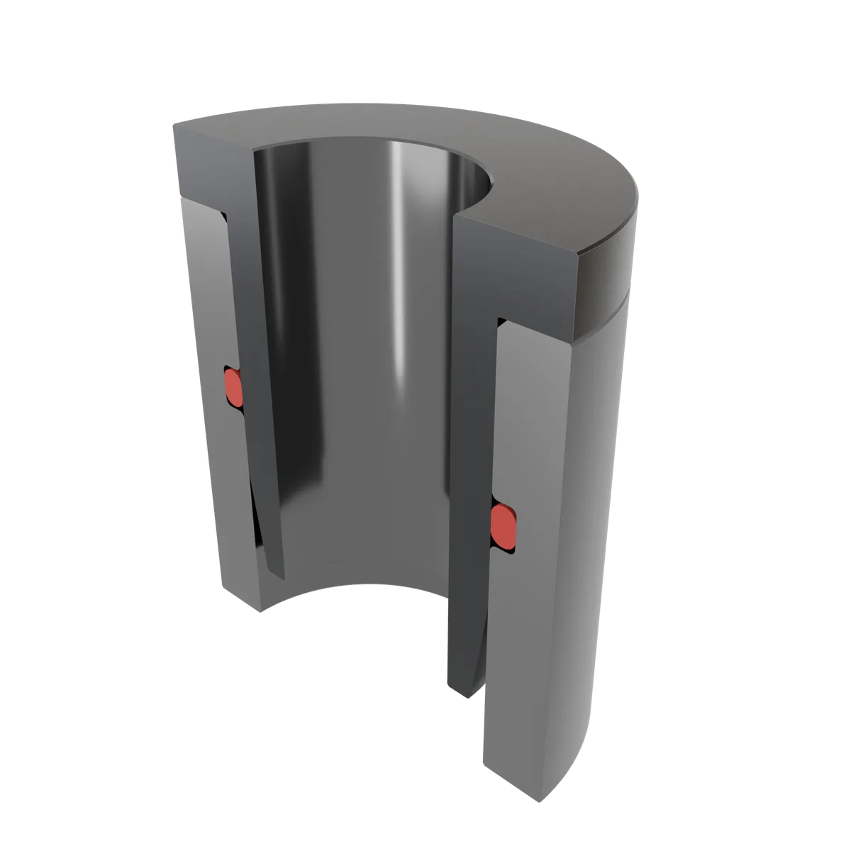
It results from the gap dimension between piston and cylinder, the cord thickness of the O-ring and the depth of the installation groove. Rod seals are inward-sealing.
1. Materials
As with the piston seal, the individual stress profile determines which materials are suitable. Taking friction, process media, temperatures and pressure into account, the designers select the O-ring grade with the best fit. Economic efficiency is also taken into consideration here.
2. Groove design
When designing the groove for a rod seal, besides the compression it is above all necessary to achieve the required, defined outer-diameter compression. For O-rings with an inner diameter below 250 mm, this outer-diameter compression should be between 1 and 3 percent; for larger dimensions, up to 5 percent. Lead-in chamfers in the inner part make installation process-reliable.
3. Installation
O-rings must be compressed in order to install them in a rod seal. A particularly gentle approach is important here so that the sealing element is not damaged. Installation succeeds best by first placing one half of the seal in the groove before the remaining part is carefully pushed in afterwards with a tool.
4. Fields of application
Dynamically stressed rod seals are found above all in hydraulics and pneumatics. There they are secured with back-up rings at high pressures. For this purpose, however, not only O-rings but also special asymmetrically shaped groove rings are used. Outward-sealing systems are often preferred over the rod seal because of the more economical manufacturing options.
Frequently asked questions
What is the difference between axial and radial compression?
When is a flange seal suitable?
How do the piston seal and rod seal differ?
Which materials are suitable for dynamic seals?
How much stretching or compression is permissible during installation?
Why are lead-in chamfers important?
