
O-ring design: groove and installation dimensions
The design phase sets the course for reliable, long-lasting sealing. Anyone who carefully matches dimension, material and groove to one another finds the optimum balance between cost and sealing performance.

- Target value for compression: around 20 percent of the cord thickness, roughly 10 percent less for FFKM.
- Select the dimension and installation space to standard in accordance with ISO 3601; this ensures availability and defined tolerances.
- Always assess temperature limits in relation to the medium, not in isolation.
- Under pressure the rule is: high pressure requires high hardness and a minimal sealing gap to avoid gap extrusion.
- FEP-encapsulated O-rings as well as VMQ and FVMQ are not suitable for dynamic applications.
Working principle: compression
The functionality of an O-ring seal revolves entirely around the compression of the sealing element between the contact faces. This lets the O-ring compensate for irregularities in the surfaces and for eccentric positioning.
In general, the target value for the deformation of the O-ring between the sealing faces is 20 percent of the cord thickness. The right groove depth and width ensure that the O-ring reliably closes the sealing point even when it shrinks due to media exposure or when the component tolerances combine unfavourably at certain points.
At the same time, the seal remains robust against pressure-induced migration of the O-ring.
O-ring tables as a guideline for the dimension
Cord thickness and diameter are the two defining properties for the dimension of an O-ring. Together with the depth of the installation groove, they determine the compression in the installed state. Using standard-compliant O-rings offers decisive advantages here:
- Standardized O-rings have the best availability.
- Purchasers can rely on standardized tolerances for the finished parts.
- Tables specify the installation spaces for standard-compliant O-rings.
The standard list from ISO 3601 has developed into the worldwide, cross-industry standard for O-rings. It links tables for the dimensions of O-rings with the suitable installation spaces for various applications.
This allows designers to determine the optimum O-ring dimension for a given installation space, and equally to work backwards from the O-ring to the required installation space. Always with the aim of keeping the compression of the sealing element within the target range. You will find the appropriate values in our O-ring table and in the O-ring groove calculator.
Temperature and media determine the material selection
Every elastomer has its ideal temperature range. Within this range, service life is at a high level because the seal-relevant material properties remain stable. Particularly high or low temperatures must be taken into account in O-ring design, as they can have a negative effect on the sealing effect. For this reason, both the lower and the upper temperature operating limit must be considered in the design.
Excessively high temperature
Excessive heat causes O-rings to permanently lose their elasticity. The ageing process usually begins with pronounced expansion of the sealing element. The increased compression results in significantly greater friction, especially in dynamic applications. This mechanical load can cause the O-ring to lose material.
In the cold state, this material is then missing to ensure the necessary minimum level of compression. After cooling down following excessive heat, the O-rings also no longer return fully to their original shape. Added to this is the effect of post-vulcanization at high temperatures: additional bonds form between the molecules that permanently disrupt the flexible behaviour of the O-ring.
Excessively low temperature
Below the material-specific glass transition temperature, O-rings lose their elasticity and their mechanical load-bearing capacity. However, this process is reversible, so the properties return once the temperature load subsides.
Nevertheless, there is a risk that the seal fails at low temperatures. If, for example, particularly high pressure peaks or external impacts act on the sealing system during the temperature exposure, the O-ring cannot adequately bridge the changed sealing gap.
Always consider temperature in relation to the medium
The temperature resistance of O-rings can only be assessed in relation to the relevant media. The general temperature range of FKM, for example, lies between −25 and +200 °C. However, this figure is based on air as the surrounding medium. If, instead, an EPDM O-ring is exposed to hot water, its long-term durability already drops significantly from 120 °C.
Media can affect sealing materials in two ways and thereby disrupt the original mode of operation:
- Physical change: Media penetrate the sealing material or leach out compound constituents such as plasticizers. These processes change the volume of the O-ring. Through shrinkage, the compression can decrease to the point where leaks occur. If the O-ring swells, mechanical properties such as hardness or tear strength change.
- Chemical change: The chemical influence relates to the bonds of the polymers. In the initial state, these give the O-ring its good sealing properties. Aggressive media split these polymer chains, so that the O-ring becomes hard and brittle.
| Material | Temperature resistance | Chemical resistance | Elasticity |
|---|---|---|---|
| FFKM | −40 °C to +340 °C | High | High |
| FEP-encapsulated | −60 °C to +200 °C | High | Medium |
| FKM (VITON) | −25 °C to +200 °C | Medium | High |
| PTFE | −250 °C to +250 °C | High | Low |
| NBR | −30 °C to +120 °C | Low | High |
| HNBR | −30 °C to +150 °C | Medium | High |
| EPDM | −45 °C to +150 °C | Medium | High |
| Silicone | −60 °C to +200 °C | Low | High |
| FVMQ | −60 °C to +200 °C | Medium | High |
| FEPM | −10 °C to +200 °C | Medium | High |
| CR | −40 °C to +100 °C | Low | High |
| ACM | −20 °C to +150 °C | Medium | High |
The most important materials and their application profile
Different operating temperatures and media narrow down the field of suitable sealing materials during the design. In addition to the general suitability profiles, more detailed areas of application can be derived for practical use:
Optimum design: groove geometry
For standard-compliant O-rings, the optimum width and depth of the groove can be read from the respective tables. Designers should also take the specific requirements of certain materials into account. For FFKM, for example, the target range for compression is about 10 percent below the otherwise usual value.
Recommended groove width (NB) and groove depth (NT) per cord thickness, separated by sealing type and static or dynamic application. All dimensions in millimetres, guide values for the design.
| Cord thickness mm | Flange seal | Piston seal | Rod seal | |||||||
|---|---|---|---|---|---|---|---|---|---|---|
| static | static | dynamic | static | dynamic | ||||||
| NB | NT | NB | NT | NB | NT | NB | NT | NB | NT | |
| 1.00 | 1.90 | 0.70 | 1.58 | 0.70 | 1.58 | 0.85 | 1.58 | 0.70 | 1.58 | 0.85 |
| 1.50 | 2.80 | 1.10 | 2.19 | 1.05 | 2.19 | 1.27 | 2.19 | 1.05 | 2.19 | 1.27 |
| 1.78 | 3.20 | 1.30 | 2.53 | 1.30 | 2.53 | 1.50 | 2.53 | 1.30 | 2.53 | 1.50 |
| 2.00 | 3.40 | 1.50 | 2.78 | 1.50 | 2.78 | 1.65 | 2.78 | 1.50 | 2.78 | 1.65 |
| 2.50 | 3.90 | 1.90 | 3.37 | 1.90 | 3.37 | 2.12 | 3.37 | 1.90 | 3.37 | 2.12 |
| 2.62 | 4.00 | 2.00 | 3.51 | 2.00 | 3.51 | 2.22 | 3.51 | 2.00 | 3.51 | 2.22 |
| 3.00 | 4.60 | 2.30 | 3.98 | 2.30 | 3.98 | 2.55 | 3.98 | 2.30 | 3.98 | 2.55 |
| 3.53 | 5.30 | 2.70 | 4.67 | 2.70 | 4.67 | 2.95 | 4.67 | 2.70 | 4.67 | 2.95 |
| 4.00 | 6.00 | 3.10 | 5.23 | 3.10 | 5.23 | 3.30 | 5.23 | 3.10 | 5.23 | 3.30 |
| 4.50 | 6.50 | 3.50 | 5.90 | 3.50 | 5.90 | 3.80 | 5.90 | 3.50 | 5.90 | 3.80 |
| 5.00 | 7.40 | 3.90 | 6.48 | 3.90 | 6.48 | 4.30 | 6.48 | 3.90 | 6.48 | 4.30 |
| 5.33 | 7.60 | 4.20 | 6.86 | 4.20 | 6.86 | 4.60 | 6.86 | 4.20 | 6.86 | 4.60 |
| 5.50 | 7.60 | 4.40 | 7.05 | 4.40 | 7.05 | 4.80 | 7.05 | 4.40 | 7.05 | 4.80 |
| 6.00 | 8.00 | 4.80 | 7.59 | 4.80 | 7.59 | 5.20 | 7.59 | 4.80 | 7.59 | 5.20 |
| 7.00 | 8.70 | 5.70 | 8.68 | 5.80 | 8.68 | 6.00 | 8.68 | 5.80 | 8.68 | 6.00 |
| 8.00 | 9.80 | 6.70 | 9.88 | 6.80 | 9.88 | 7.00 | 9.88 | 6.80 | 9.88 | 7.00 |
| 9.00 | 11.20 | 7.60 | 11.14 | 7.70 | 11.14 | 7.90 | 11.14 | 7.70 | 11.14 | 7.90 |
| 10.00 | 12.20 | 8.60 | 12.38 | 8.60 | 12.38 | 8.80 | 12.38 | 8.60 | 12.38 | 8.80 |
NB Groove width · NT Groove depth · all values in mm. Guide values for groove design; the decisive factors are material, tolerances and operating conditions. Check dimensions with our O-ring groove calculator.

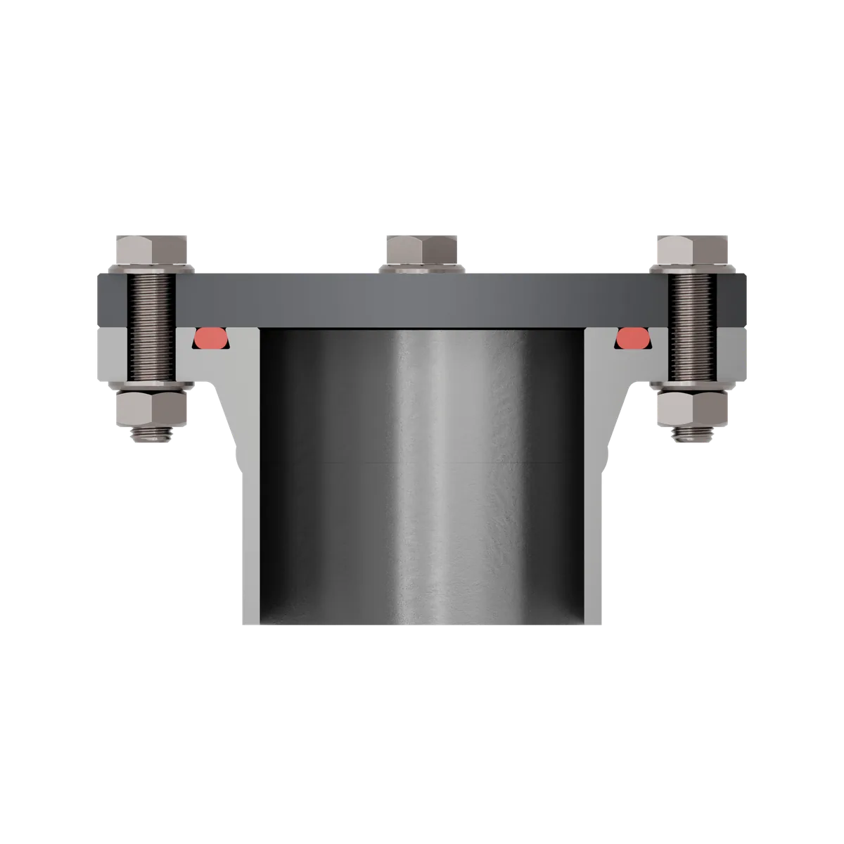
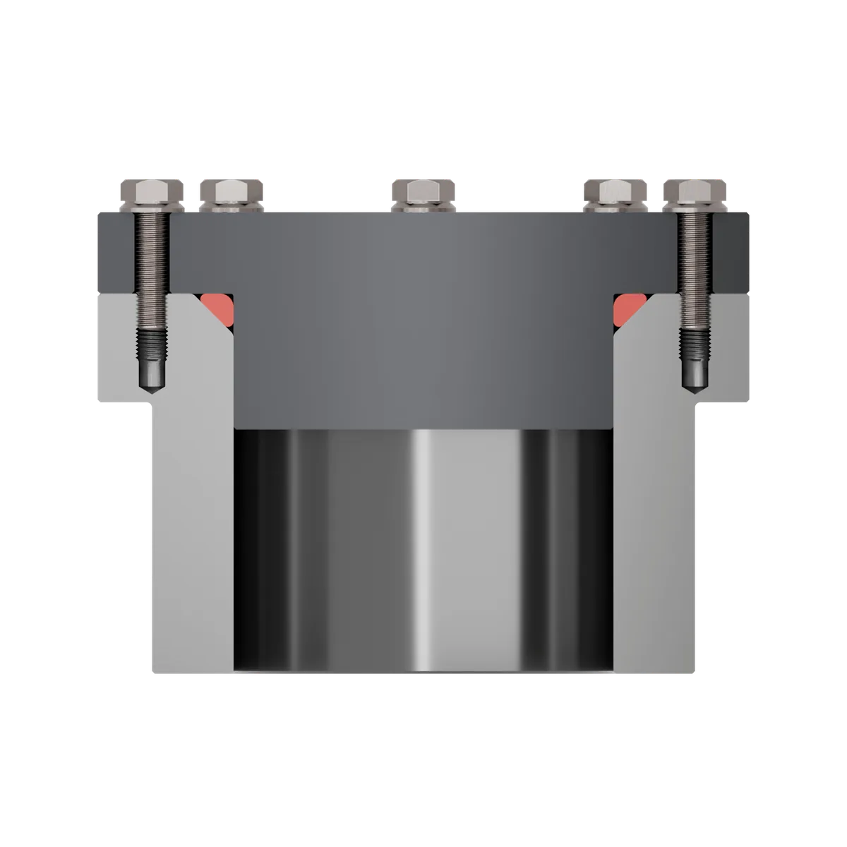
Especially for larger cord thicknesses, the design should ensure a lower compression via the groove. You will find the specific table values for flange, piston and rod seals in the O-ring groove and in the O-ring groove calculator. Which tolerances apply to the installation space and O-ring is explained in the article on O-ring tolerances.
Optimum design: system pressure
When designing a pressurized groove, four things are important:
- The level of pressure
- The direction of pressure
- The Shore hardness of the O-ring
- The size of the sealing gap
This gives rise to three basic rules:
- High pressure: high hardness of the O-ring and a minimal sealing gap.
- Pressure from inside: design the O-ring with compression at the outer diameter.
- Pressure from outside: design the O-ring with stretch at the inner diameter.
High system pressures and changing pressure conditions call for particular care. Via the groove width, the design determines the extent to which the O-ring can migrate within the groove. Especially under changing conditions, movement towards the side facing away from the pressure can cause mechanical wear.
The sealing gap also requires particular attention. If it is smaller, this reduces the risk of gap extrusion, in which parts of the O-ring are sheared off at the groove edge. Materials with high hardness are less susceptible to this. More on this in the article O-rings under pressure.
The following table helps with choosing the optimum Shore hardness under pressure. It is based on a cord thickness of 2 mm. As a general rule: the greater the cord thickness, the larger the sealing gap may be.
| O-ring hardness | Pressure level | Sealing gap |
|---|---|---|
| 70 Shore A | 0-50 bar | 0.06 mm |
| 70 Shore A | 50-100 bar | 0.03 mm |
| 70 Shore A | 100-200 bar | Do not use |
| 80 Shore A | 0-50 bar | 0.08 mm |
| 80 Shore A | 50-100 bar | 0.05 mm |
| 80 Shore A | 100-200 bar | 0.02 mm |
| 90 Shore A | 0-50 bar | 0.11 mm |
| 90 Shore A | 50-100 bar | 0.06 mm |
| 90 Shore A | 100-200 bar | 0.03 mm |
Static and dynamic applications
Back-up rings are suitable above all for static seals. However, that is not the only difference between static and dynamic applications. Some materials are barely suitable for dynamic use from the outset because they are too susceptible to abrasion. Other materials can be used without any problem, in which case a lower compression should be chosen.
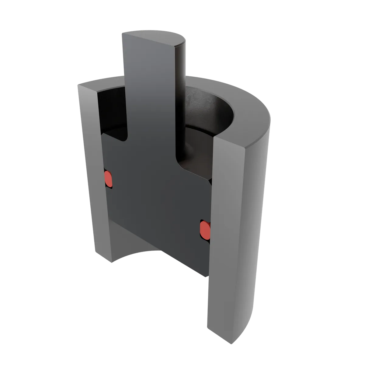
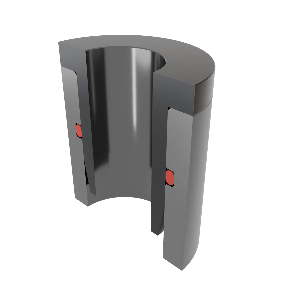
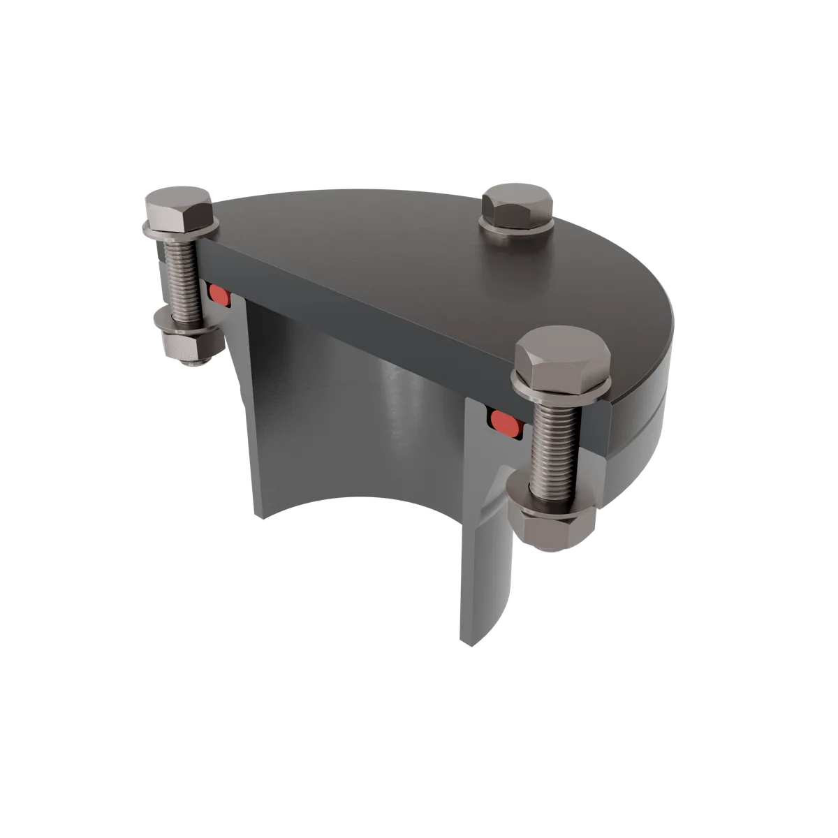
As a general rule, FEP-encapsulated O-rings as well as VMQ and FVMQ are not suitable for dynamic applications. All other O-ring materials can be used in dynamic applications.
Optimum design for greater cost-effectiveness
With O-ring seals, cost-effectiveness is not determined by the cost of producing the installation groove or procuring the O-rings. In the long term, a reliable operating phase has an enormously positive effect on total costs. One-off savings during purchasing, by contrast, can quickly evaporate.
Therefore, the design should be geared from the outset towards creating optimum conditions for a long service life through coherent material selection, careful groove geometry and specific consideration of the operating conditions.
Frequently asked questions
How high should the compression of an O-ring be?
Why should I use standard-compliant O-rings in accordance with ISO 3601?
What temperature can an FKM O-ring withstand?
How does the system pressure affect the O-ring design?
What is gap extrusion and how do I avoid it?
Which O-ring materials are not suitable for dynamic applications?